Method for obtaining field strength information

a field strength and information technology, applied in the field of field strength information and circuit arrangement, can solve the problem of insufficient spatial resolution, and achieve the effect of low signal voltage to noise voltage ratio, low power consumption, and increased amplification

Active Publication Date: 2012-06-12
ATMEL CORP
View PDF18 Cites 4 Cited by
  • Summary
  • Abstract
  • Description
  • Claims
  • Application Information

AI Technical Summary

Benefits of technology

[0012]An advantage of the method or the circuit arrangement is that the field strength of the received electromagnetic signal can be determined, preferably without further calculations, in a simple manner from a comparison of the selected divider node and stored field strength values, assigned beforehand to the particular divider node. As a result, the method can be used for determining the spatial distance, i.e., the distance between the receiver unit and a transmitting unit, by linking the field strength values, assigned in the value table to the respective divider nodes, to a distance value. Further, by means of the values, determined in such a way, for the field strength or the distance, the data rate can be changed, for example, increased with the decline in the distance and vice versa. Further, because of the low power consumption, the method is especially suitable for obtaining field strength information in the case of passive transponders. The method of the invention is based, inter alia, on the fact that the field strength is linked to the distance between a receiver station and a transmitter station by a nonlinear functional relation. The nonlinear relation can be compensated substantially inversely proportional by the suitable realization of different resistance values of components connected between the particular divider nodes of the voltage divider circuit. In this case, the data of the connected components are accordingly determined beforehand, in order to reproduce the described functional relation between field strength and distance, so that a line as straight as possible results in a preferably linear plot of the divider node number versus the logarithm of the distance between the receiver and the base station. Because the amplification of the operational amplifier remains constant, the output voltage of the operational amplifier has a fixed ratio to the input voltage. As a result, neither at low input voltages nor at high input voltages is the amplification increased and the ratio of the signal voltage to the noise voltage remains low over the entire amplification range. Another important advantage is that over the entire detectable distance range there is an almost uniform spatial resolution both at small distances to the transmitting station and at great distances to the transmitting station.
[0013]Another advantage is that the value of the input resistance of the voltage divider circuit does not change with the change in the input voltage. The voltage divider circuit functions comparably to a potentiometer with a center tap. It is understood that the input resistance of the operational amplifier is very high, so that the current, flowing from a selected node connected to the operational amplifier, is negligibly small. Overall, a change in the load at an antenna circuit, connected upstream of the receiver circuit, is avoided. In particular, during use in a transponder, the input voltage source, therefore the antenna circuit, is constantly loaded and the quality of the antenna circuit in particular is not changed. This is an important advantage in an inductively coupled antenna circuit. Tests by the applicant have shown that the voltage divider circuit, i.e., the input resistance, can be made very high-impedance. This is advantageous specifically in circuits operating passively, i.e., those that draw the needed power exclusively from the electromagnetic field of a transmitting station, in order to increase the communication range between a receiver and a transponder operating according to the method of the invention.
[0014]Further, particularly with varying signal levels, a rapid turn-on and turn-off transient behavior at the output of the operational amplifier is achieved, because the output voltage and the input voltage of the operational amplifier fluctuate only to a minor extent and the capacitances, present at the input or output of the operational amplifier, are not recharged and the power consumption of the circuit unit declines. In particular, in the case of pulse-pause modulated signals, the field gaps can be reduced by the short turn-on and turn-off transient behavior and the data rate increased. Another advantage of the fixed amplification factor is that in the case of the operational amplifier, the amplification can be adjusted precisely with a low current consumption by means of a high-impedance negative feedback.
[0018]According to another embodiment, it is advantageous that in each case two resistance values, compared with one another, between two divider nodes form a logarithmic relationship. As the value of the field strength in zero approximation is inversely logarithmic from the distance of the base station to the transponder, a substantially linear dependence between the number of the node and the distance can be achieved from the number of the node, directly by means of an assignment of the node number to an assigned distance value, preferably stored in a value table. In this case, it is advantageous, when the value of the signal, present at the output of the counter or of the control element, preferably indicates the number of the selected divider node. As a result, a sufficient accuracy or resolution in the distance determination can be established both at small and larger distances between the base station and the transponder. Further, the distance between base station and transponder can be determined without additional calculations by means of the values stored in the value table, also independent of the selected relationship of two resistance values. In summary, the method for determining the field strength can be easily refined into a method for determining the distance between the base station and transponder.

Problems solved by technology

Because of the fixedly predefined values of the resistance branches of the parallel circuit, the spatial resolution is very different depending on the distance; the spatial resolution is insufficient particularly at a small distance.

Method used


Image

  • Method for obtaining field strength information
  • Method for obtaining field strength information
  • Method for obtaining field strength information

Examples


Embodiment Construction

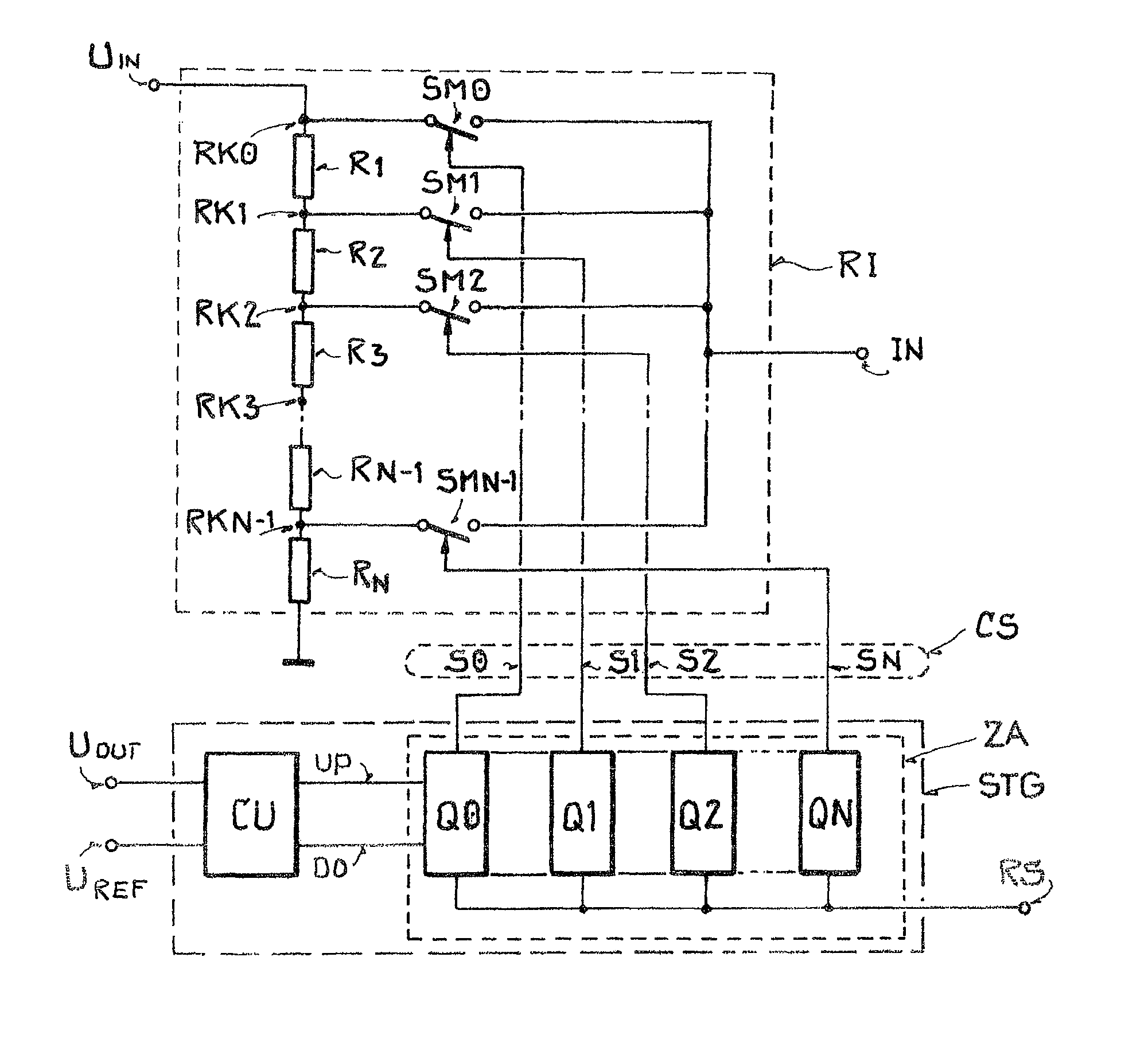
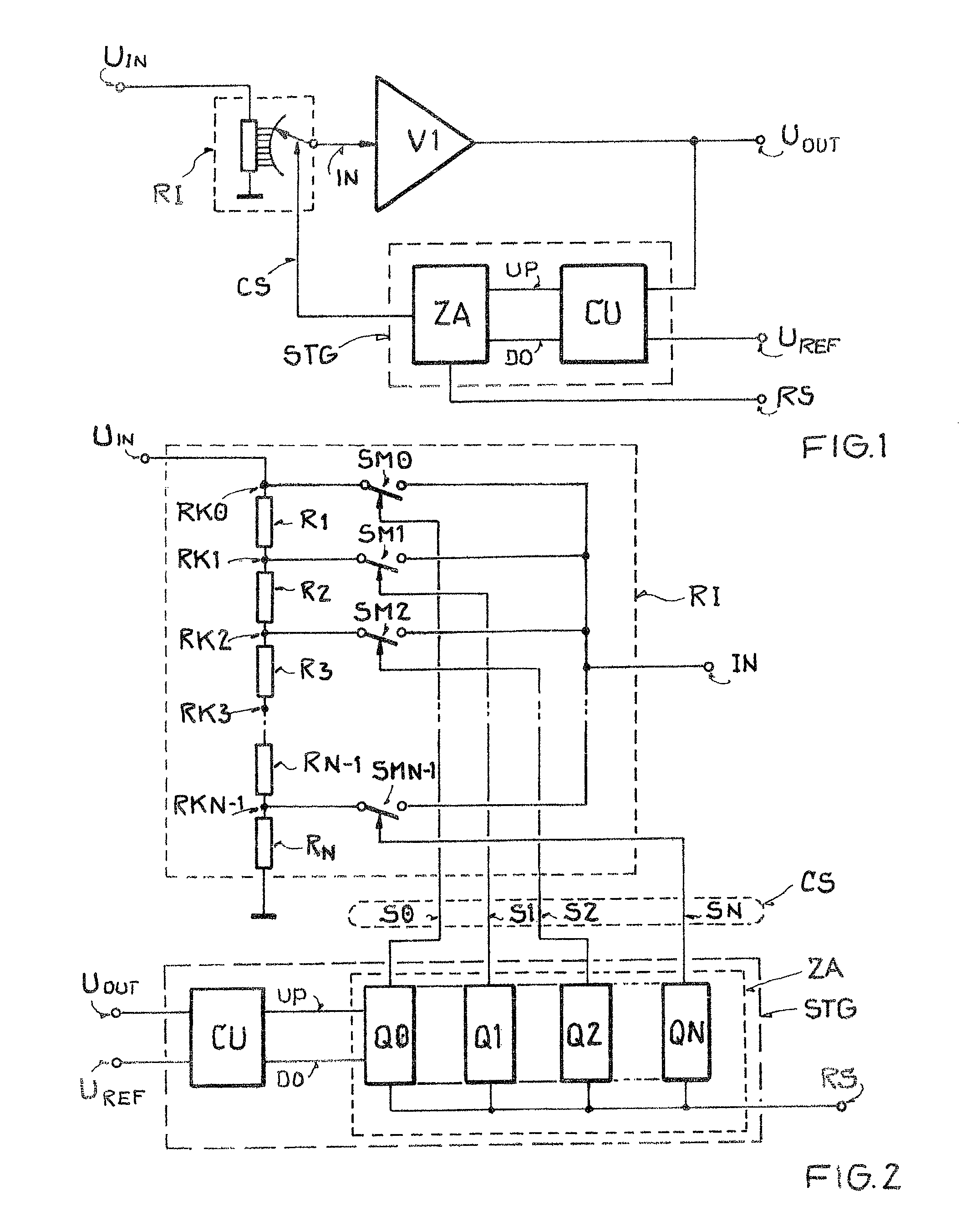
[0027]The task of the circuit arrangement, shown in FIG. 1, is to generate an input signal UIN, which has an alternating voltage form and is proportional to the field strength of an electromagnetic signal received by a receive antenna (not shown), from an input voltage IN by means of a voltage divider circuit and to amplify an operational amplifier V1 by a fixed factor, in order to hold the output signal UOUT within a predefined interval by means of a control element STG, which selects a suitable node and hereby does not change the resistance value of an input resistance RI, realized as a voltage divider. The input signal UIN declines completely across the input resistance RI.

[0028]The voltage divider circuit with a plurality of nodes has a first terminal, which is linked to the input signal UIN, a second terminal, which is linked to the reference potential, a third terminal, which is formed as a control input and is linked to the control element STG and at which a control signal CS...


PUM


Abstract

A method for obtaining field strength information from a received electromagnetic signal by a receiver unit is provided, whereby an input voltage for an operational amplifier is generated from the received signal in the receiver unit by means of an input resistance realized as a voltage divider circuit and an output voltage is generated by the operational amplifier by means of a fixed amplification factor. The input voltage is changed until the output voltage lies within a predefined interval that includes the value of the reference voltage. The input voltage is tapped at the voltage divider circuit and, to change the input voltage at the voltage divider circuit, which has a plurality of divider nodes and a constant resistance value, a divider node is selected and a partial voltage is tapped. The field strength value received by the receiver unit is determined from a comparison of a quantity assigned to the selected divider node.

Description

[0001]This nonprovisional application claims priority to German Patent Application No. DE 10 2009 021 153.5, which was filed in Germany on May 13, 2009, and to U.S. Provisional Application No. 61 / 177,805, which was filed on May 13 2009, and which are both herein incorporated by reference.BACKGROUND OF THE INVENTION[0002]1. Field of the Invention[0003]The present invention relates to a method for obtaining field strength information and to a circuit arrangement.[0004]2. Description of the Background Art[0005]A method of this type is known from European Pat. No. EP 1 318 623 B1, which corresponds to U.S. Pat. No. 6,922,553, and which is incorporated herein by reference. Inter alia, a distance between the transmitter and receiver can be determined by means of the field strength information and can be used as a means for detecting relaying. In general, a so-called “RSSI (Received Signal Strength Indicator)” value, which is related to the input signal of a receiving antenna, is determine...

Claims


Application Information

Patent Timeline
Patent Type & Authority Patents(United States)
IPC IPC(8): H04B17/00
CPCG01R15/09G01R29/0871
Inventor MOSER, DANIELSAILE, THOMAS
Owner ATMEL CORP
Why Eureka
Try Eureka