
Device for measuring interpupillary distance in a head-mounted display unit

a technology of interpupillary distance and display unit, which is applied in the field of methods and systems of measuring interpupillary distance, can solve the problems of limiting the utility of vr head-mounted units, requiring extremely large screens, and never becoming mainstream in the field of technology

Active Publication Date: 2015-04-23
VALVE
View PDF2 Cites 16 Cited by
  • Summary
  • Abstract
  • Description
  • Claims
  • Application Information

AI Technical Summary

Benefits of technology

The patent text describes a head-mounted display (HMD) that allows users to see images in a virtual reality (VR) application. The technical effect of the patent is to provide a reliable way to set the HMD lens positions that does not depend on subjective judgments, by using a pattern of projecting on the screen that the user can easily adjust to match their interpupillary distance. This compensates for the user's head movement and ensures that the image looks correct. The patent also describes a system that can quickly compensate for user's head movement by providing feedback to the user.

Problems solved by technology

For example, head mounted displays may be relatively small and compact but can display images that, if they were to be displayed on conventional fixed displays, would require extremely large screens.
Head-mount display (MHD) units used for Virtual Reality (VR) applications have existed for decades, but the technology has never become mainstream.
One factor that limits the utility of VR head-mount units is the difficulty in accurately setting the spacing between left and right displays to match the user's interpupillary distance.
A mismatch may cause eyestrain and poor 3D perception.
Some existing HMDs allow the user to manually adjust the spacing between left and right displays, but the accuracy of the adjustment is often poor since users must move the displays until the image “looks correct.” Without any feedback, the user must rely on their visual perception, which is often deceiving.

Method used


Image

  • Device for measuring interpupillary distance in a head-mounted display unit
  • Device for measuring interpupillary distance in a head-mounted display unit
  • Device for measuring interpupillary distance in a head-mounted display unit

Examples


Embodiment Construction

[0019]Those of ordinary skill in the art will realize that the following description of certain embodiments is illustrative only and not in any way limiting. Other embodiments will readily suggest themselves to such skilled persons, having the benefit of this disclosure. Reference will now be made in detail to specific implementations as illustrated in the accompanying drawings. The same reference numbers will be used throughout the drawings and the following description to refer to the same or like parts.

[0020]In general, a head-mounted display (HMD) may consist of an image projector mounted to the head that projects one or more images onto a screen in front of one or both of the user's eyes. Both the screen and the projector may be mounted onto the user's head such that they are in a fixed position relative to the user's eyes. The screen may be positioned between the projector and the user's eye in a rear-projection format or the screen may be positioned in front of both the proje...


PUM


Abstract

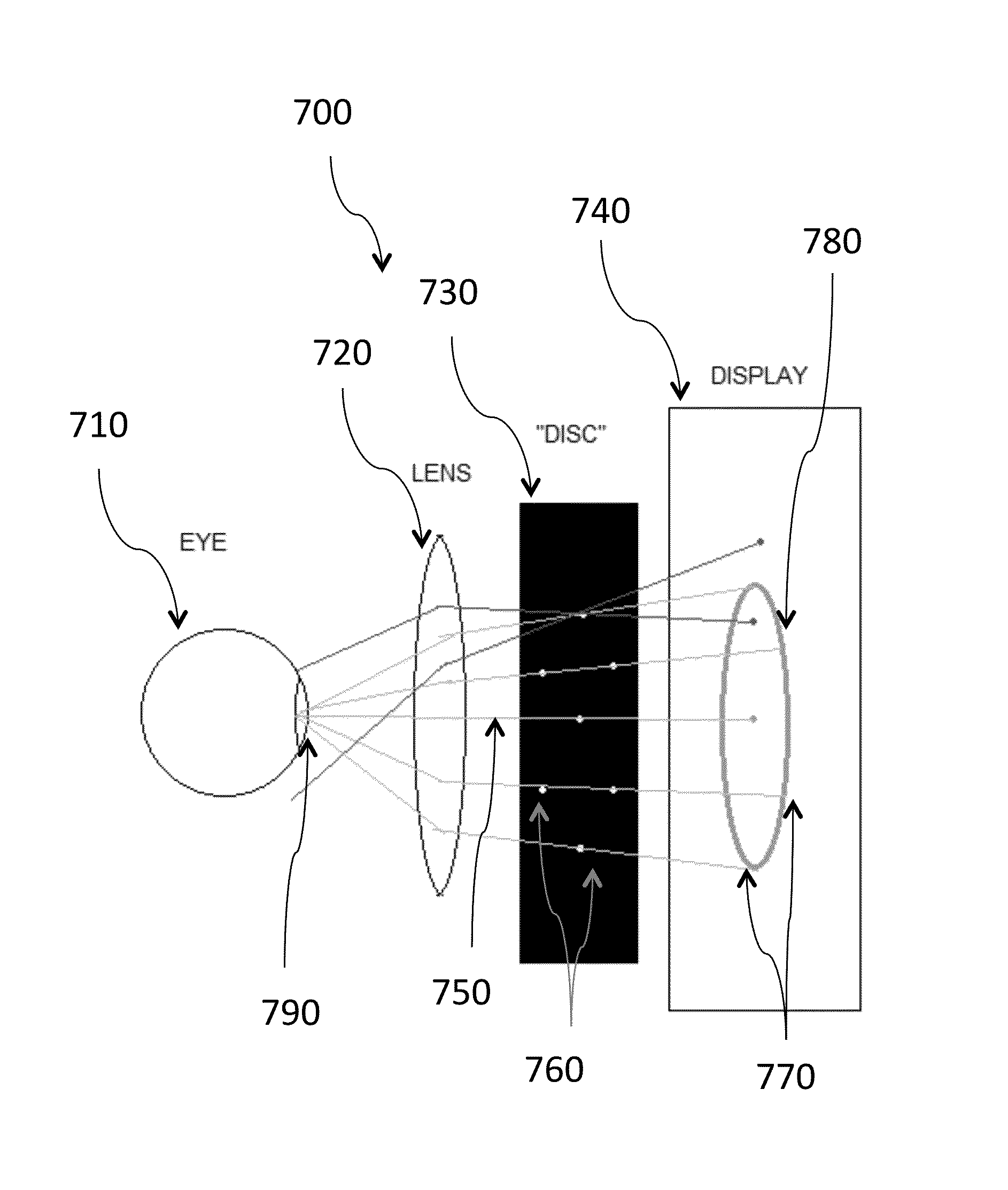
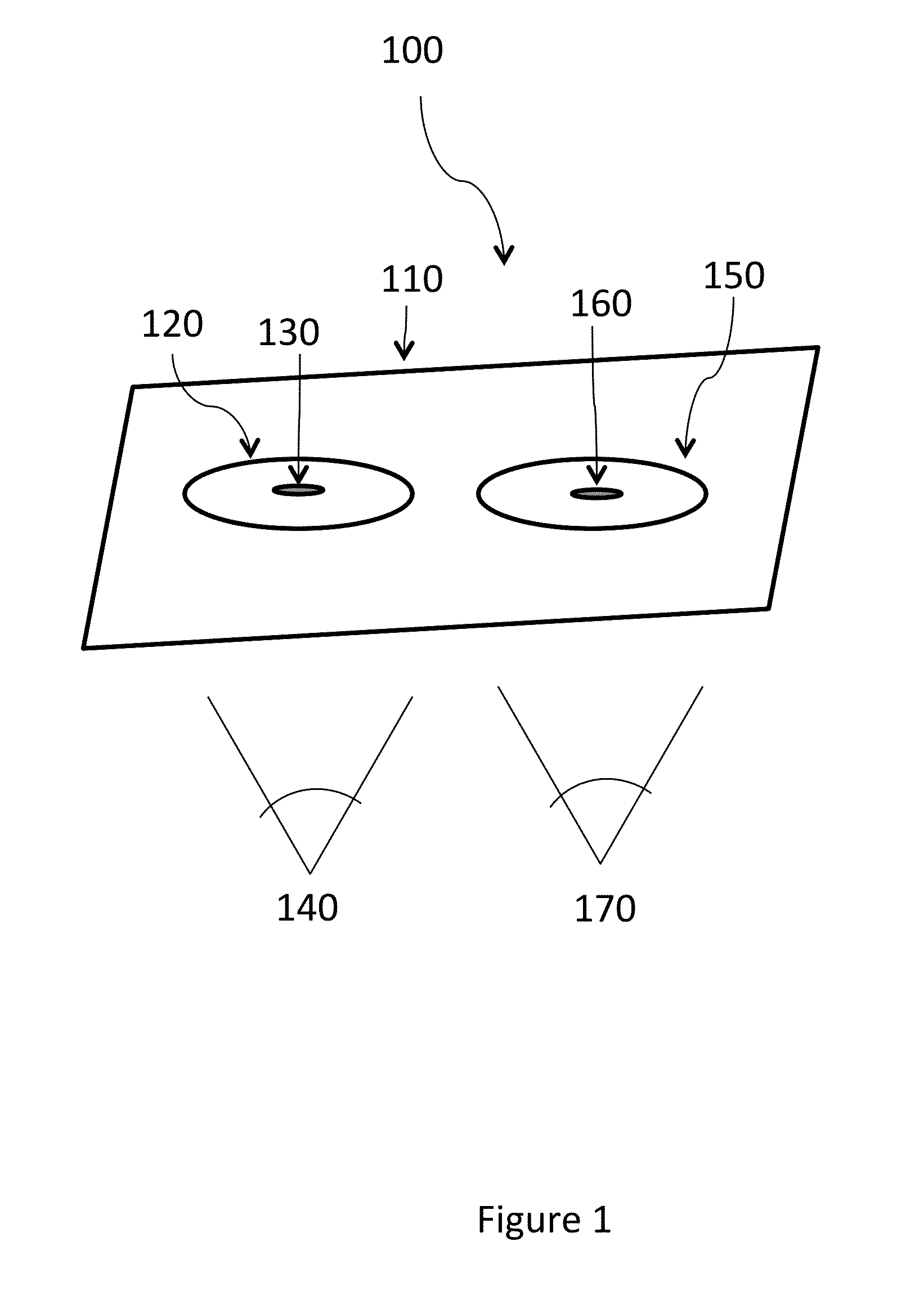
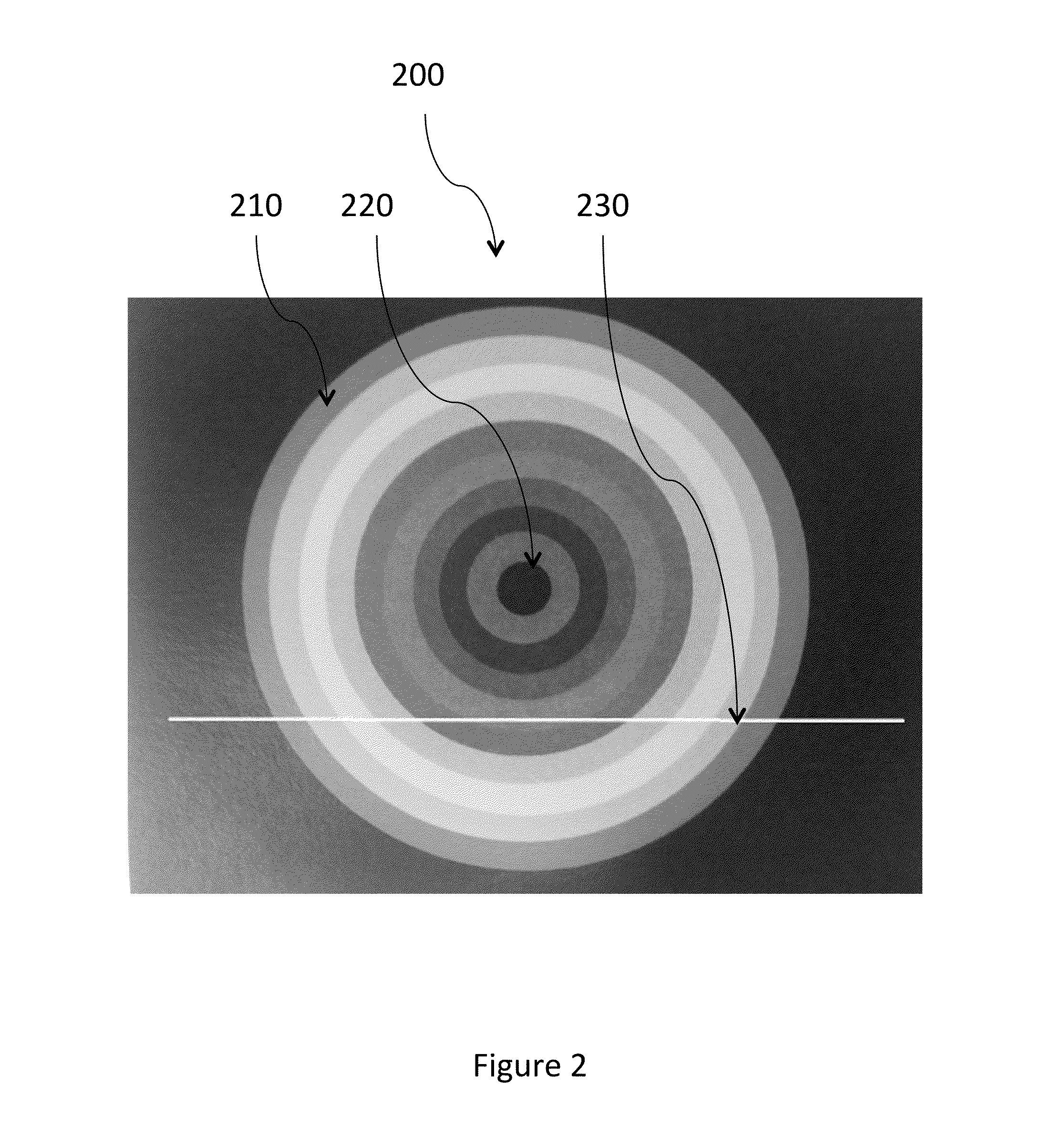
In certain embodiments, a head-mounted display may include one or more displays for displaying images. A left and right movable disk may be placed respectively between the left and right eyes of a user and the one or more displays. The user may wear the HMD, and may adjust the spacing between the left and right disks while viewing the computer-displayed image or images through holes in the plastic discs. For example, the HMD may display a stereo colored bulls eye pattern, of which the user can only see a portion because their vision is restricted to on-axis viewing by the discs. The computer may instruct the user to move the HMD disks until the user can only see the color in the center of the bulls eye. In certain embodiments, by performing the foregoing adjustment, the eye may be oriented on the proper optical axis to look through an optimal location of a lens.

Description

BACKGROUND OF THE DISCLOSURE[0001]1. Field of the Disclosure[0002]The disclosure relates generally to methods and systems of measuring interpupillary distance and positioning of a user's eyes with respect to one or more screen in a head-mounted display.[0003]2. General Background[0004]Head-mounted electronic displays have existed for many years. For example, helmet mounted displays were first deployed by the U.S. Army in the Apache helicopter in 1984. These head-mounted displays have many advantages over fixed displays. For example, head mounted displays may be relatively small and compact but can display images that, if they were to be displayed on conventional fixed displays, would require extremely large screens.[0005]Head-mount display (MHD) units used for Virtual Reality (VR) applications have existed for decades, but the technology has never become mainstream. One factor that limits the utility of VR head-mount units is the difficulty in accurately setting the spacing between ...

Claims


Application Information

Patent Timeline
IPC IPC(8): A61B3/11A61B3/024G02B27/01A61B3/00
CPCA61B3/111G02B27/0176A61B3/024A61B3/0091G02B7/12G02B27/0093G02B27/017G02B2027/0112G02B2027/0134G02B2027/014G02B2027/0154
Inventor KRASNOW, BENJAMIN DAVIDNEWELL, DAN
Owner VALVE
Learn More