
Thermometer Management System

a management system and thermometer technology, applied in the direction of temperature measurement in household appliances, instruments, wireless architecture, etc., can solve the problems of cumbersome operation, inability to make use of location advantages, and high accuracy of thermometers, etc., to achieve the effect of easy fine accuracy managemen

Active Publication Date: 2015-04-23
MIZUNO YOSHIRO
View PDF9 Cites 203 Cited by
  • Summary
  • Abstract
  • Description
  • Claims
  • Application Information

AI Technical Summary

Benefits of technology

The patent describes a system that allows for calibration of thermometers to ensure accuracy in measuring temperature. The system aims to improve the calibration process by enabling easy separation of the calibrated probe from the main thermometer, simplifying the setup process. Additionally, the system allows for individual calibration of digital probes, resulting in improved accuracy and efficiency in managing the temperature of different objects. Overall, the system promotes improved accuracy and convenience in temperature measurement.

Problems solved by technology

A highly accurate thermometer is an expensive precision apparatus.
The following problem occurs in an object in which temperatures are monitored by this type of thermometer, for example, in a chiller.
If the door of the chiller is opened for cleaning, the thermometer inside detects an error even if the work is a common maintenance work.
However, in a case of a thermometer monitoring a plurality of monitoring objects, when maintenance workers are going to stay and clean a monitoring location, it would be a cumbersome operation to access a computer working in the background and to specify a probe for which the alarm is to be cancelled.
Because computer terminals for input are not often located around monitoring objects and one cannot make use of advantages of the location.

Method used


Image

  • Thermometer Management System
  • Thermometer Management System
  • Thermometer Management System

Examples


first embodiment

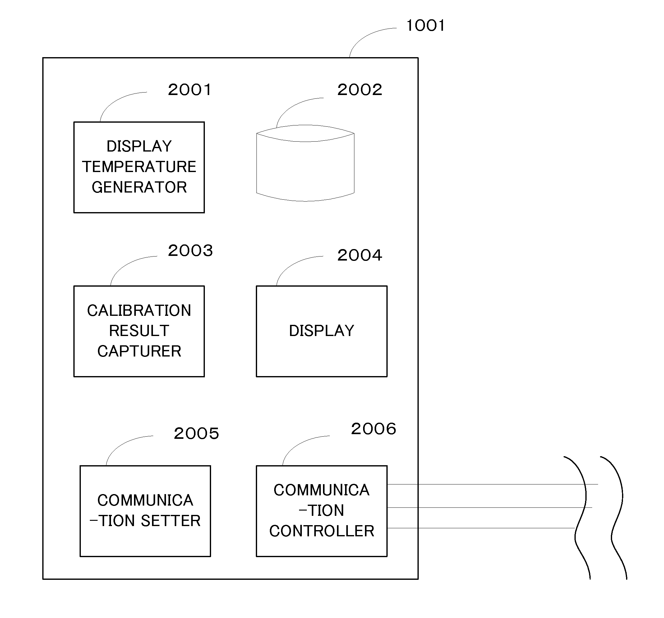
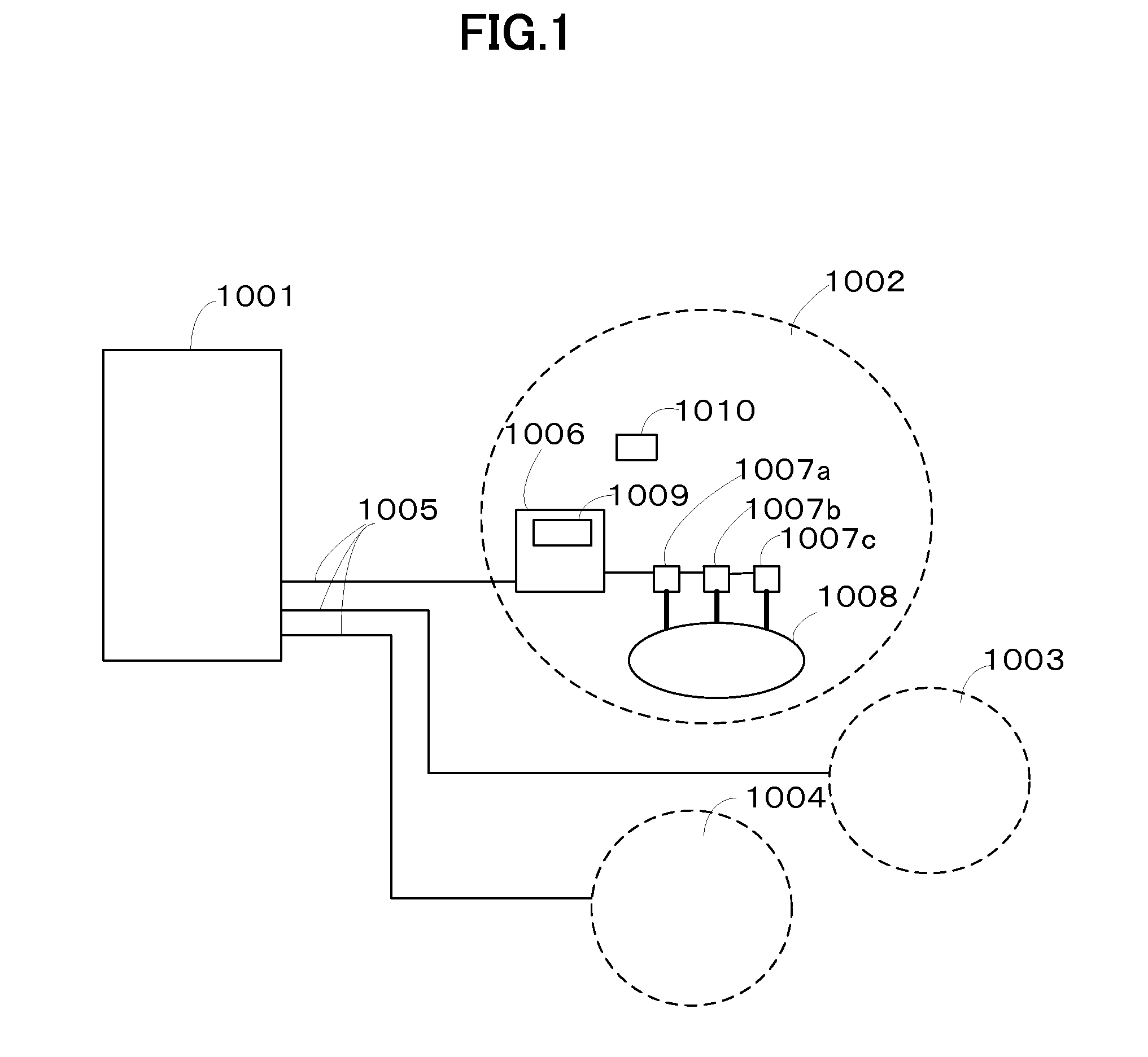
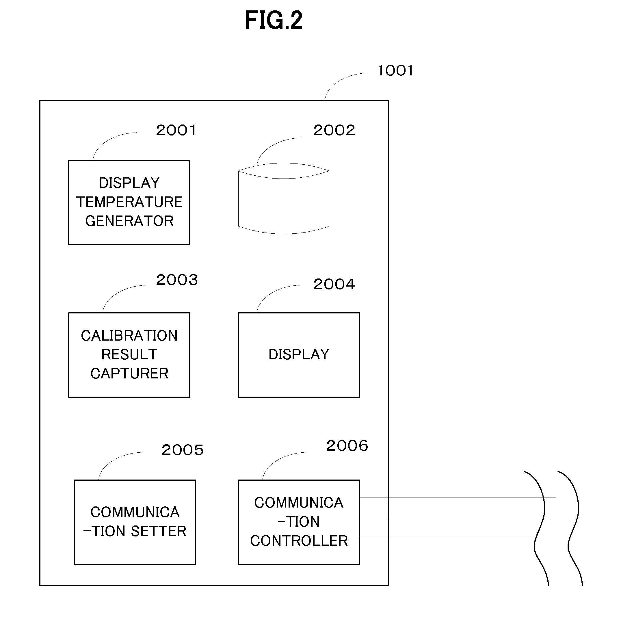
[0074]FIG. 1 is an external view showing an installation condition of a thermometer in a first embodiment. A temperature body 1001, a first location to be measured 1002, a second location to be measured 1003 and a third location to be measured 1004 are established. Although this embodiment has three locations to be measured, the number of locations to be measured of the present disclosure is not limited to three and the number can be appropriately changed depending on object to be measured and characteristics of temperature measuring works.

[0075]The three locations to be measured and the temperature body 1001 are connected via communication lines 1005. Apparatuses installed at the first location to be measured are explained in detail. The detail described here is similarly applied to the second location to be measured and the third location to be measured. The communication lines 1005 are connected to a network unit 1006. The network unit is connected to three digital probes 1007a, ...

second embodiment

[0127]FIG. 13 is an external view showing an installation condition of the thermometer in the second embodiment, a thermometer body 13001, a chamber A13002 of a first refrigerator which is the first object to be measured, an ice temperature chamber B13003 of the first refrigerator which is the second object to be measured, and a second refrigerator 13004 which is the third object to be measured are established in the second embodiment. Each object to be measured here is established at distant locations to be measured. Each location to be measured and the thermometer body 13001 are connected via communication lines 13005.

[0128]Apparatuses installed at the first location to be measured are explained in detail. The communication lines 13005 are connected to a network unit 13006. The network unit is connected to a digital probe 13007 and relays the digital output from the digital probe to the communication lines. The digital probe is fixed with regard to the chamber A13002 to be measure...


PUM

PropertyMeasurementUnit
temperatureaaaaaaaaaa
temperaturesaaaaaaaaaa
constant temperatureaaaaaaaaaa

Abstract

A body of a thermometer (1001), a first location to be measured (1002), a second location to be measured (1003) and a third installation location (1004) is established by the thermometer management system. Further, communication lines (1005) are connected to network units at each location to be measured. Network units relay the sensor output from a sensor part to the communication lines. A sensor part is fixed to an object to be measured and sends a sensor output in response to the temperature of the object to be measured. A network unit has a radio frequency identifier (RFID) reader and transmits to the thermometer body commands and the like stored in the memory of an RFID card in response to approach of the RFID card arranged corresponding to a location to be measured. The thermometer body receives the commands and the like and performs predetermined operations.

Description

TECHNICAL FIELD[0001]The present disclosure relates to a management system for a thermometer, and particularly to a management system for a thermometer that receives digital output of a digital probe of a thermometer and generates a display temperature in reference to the digital probe's temperature characteristics of the digital probe being stored in a predetermined memory device.[0002]The digital probe here is a term used to indicate a sensor part that converts output of a heat sensor element to output digital signals.BACKGROUND ART[0003](Accuracy Management)[0004]A highly accurate thermometer is an expensive precision apparatus. When degradation of temperature characteristics is probable, from an economical and reasonable point of view, it is common that accuracy management is performed by calibrating thermometers, not by replacing thermometers. A standard calibration procedure is as follows. That is, removing the thermometer from an object to be measured, carrying the thermomete...

Claims


Application Information

Patent Timeline
Patent Type & Authority Applications(United States)
IPC IPC(8): G01K15/00G01K1/02
CPCG01K1/02G01K15/005G01K1/024G01K1/026G01K2207/06H04Q9/00H04Q2209/47H04Q2209/823
Inventor MIZUNO
Owner MIZUNO YOSHIRO
Learn More