Spinal implant kit

Inactive Publication Date: 2006-07-06
SPINAL
View PDF99 Cites 33 Cited by
  • Summary
  • Abstract
  • Description
  • Claims
  • Application Information

AI Technical Summary

Benefits of technology

[0016] The surgical kit is composed of one or more bone plate(s) for stabilizing adjacent vertebrae and several different fasteners for penetrating and securing the plate(s) to

Problems solved by technology

The interface between the bone screws and the bone presents problems of stability and long term usage that have been addressed in different ways.
Severe back-out results in the bone screw working itself out of the bone and/or plate resulting in instability of the bone or joint.
This situation results in increasing pain and danger from the instability, as well

Method used


Image

  • Spinal implant kit
  • Spinal implant kit
  • Spinal implant kit

Examples


Embodiment Construction

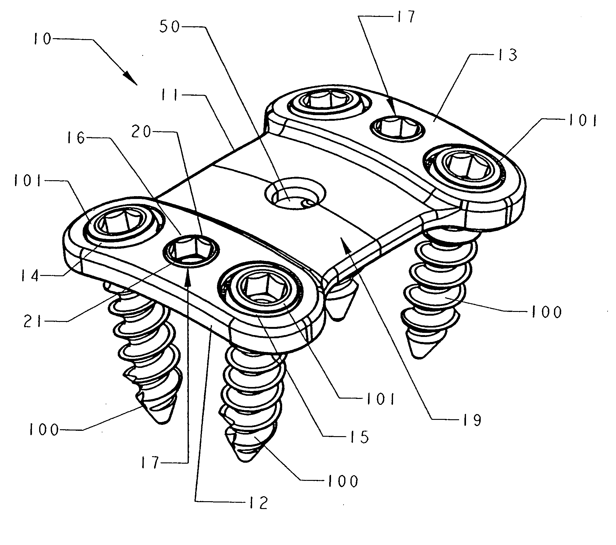
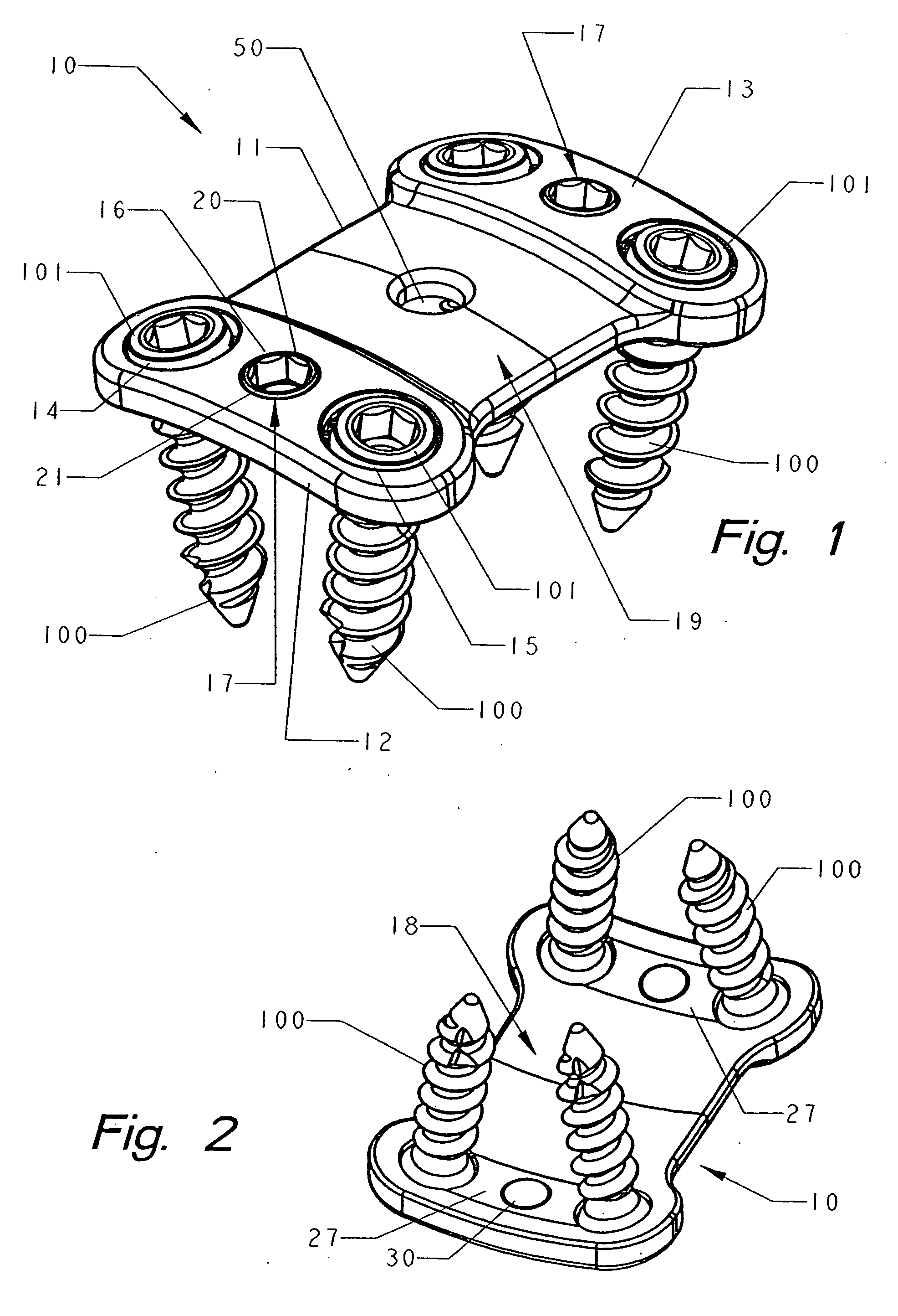
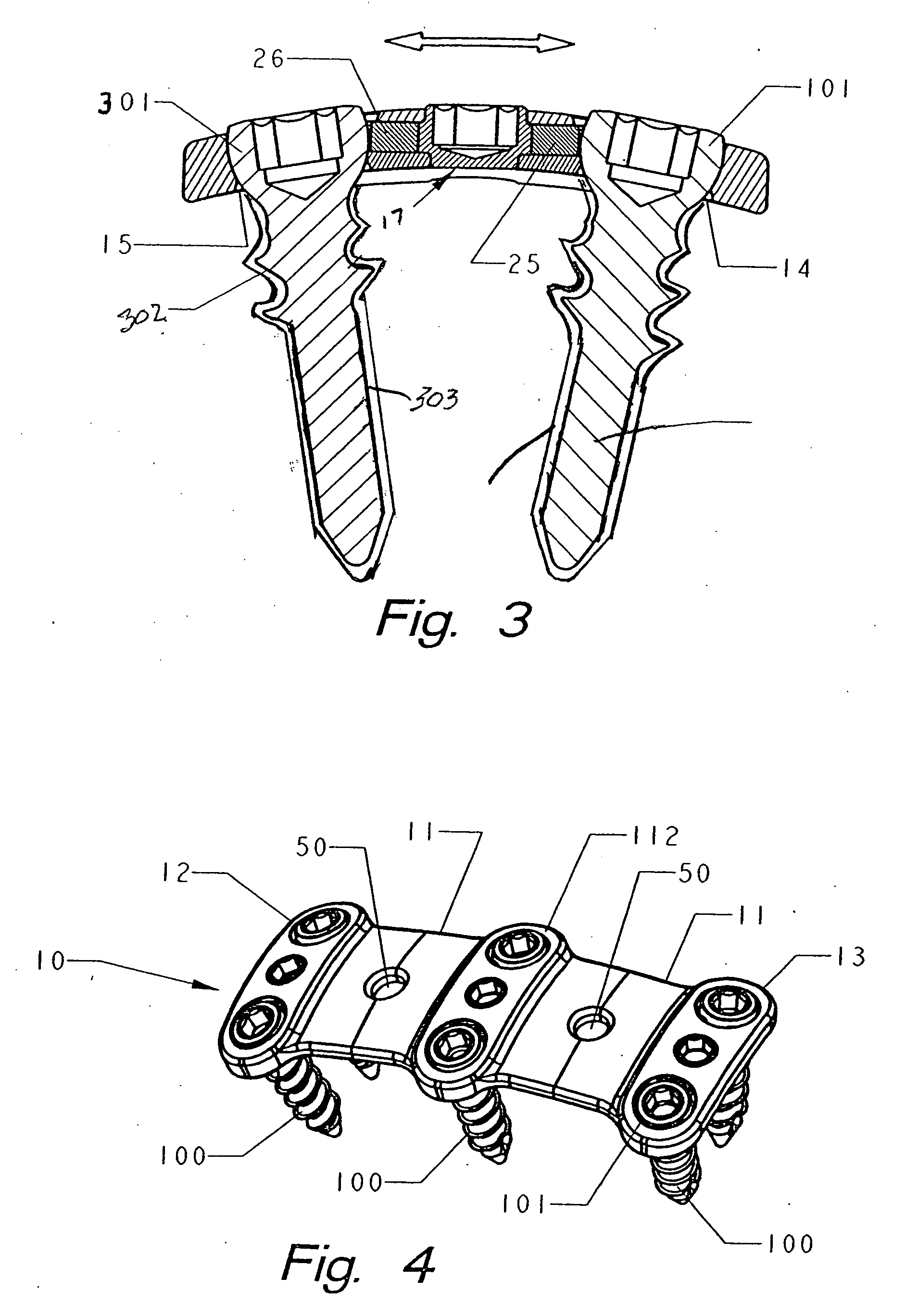
[0033] The bone plate 10, shown in FIGS. 1, 2, and 4, is based on an elongated span 11 having a first end and a second end with a first bracket 12 on the first end adapted to engage a first vertebrae and a second bracket 13 on the second end adapted to engage a second vertebrae. The first bracket includes a first bone fastener aperture 14 and a second bone fastener aperture 15 with a cam bore 16 located therebetween, each bone fastener aperture being countersunk. Screw threaded fasteners 100 are shown in place with the screw heads 101 resting in the countersunk apertures. This contributes to the low profile of the implant preventing undue trauma to the tissue on the anterior aspect of the cervical spine. A rotating eccentric cam 17, shown in FIG. 8, is mounted in the cam bore.

[0034] The second bracket 13 has the same components as the first bracket 12. An aperture 50 is located in the span 11 to facilitate boney ingrowth to increase stability. In FIG. 4, a bone plate 10 is shown wi...


PUM


Abstract

A bone plate kit for stabilizing adjacent vertebrae or ends of a bone includes several bone plates of different sizes and several bone fasteners of the same or different sizes. The fasteners may have the same configuration or several different configurations. The fasteners may be coated with bone growth material. The plates have a span for extending across a discontinuity. The span has brackets for attaching to the bone. The brackets have countersunk apertures terminating through which bone screws are placed in the bone. An eccentric cam bore is located between the countersunk apertures and, upon rotation of an eccentric cam, wedge grip shoes are slid into the countersunk apertures and frictionally engage the spherical heads of the bone screws. To prevent back-out of the bone screws, the eccentric cam is locked into the wedge grip shoes.

Description

RELATED APPLICATIONS [0001] This application is a continuation in part of U.S. patent application, Ser. No. 11 / 031,143 filed Feb. 4, 2005, which is incorporated herein by reference.FIELD OF THE INVENTION [0002] This invention relates to the field of orthopedic surgery and to kits, eg., surgical trays, including bone plates and screws or other fastening devices by which the plates are secured to the bone. BACKGROUND OF THE INVENTION [0003] The use of bone pins and plates for reducing fractures is well known in orthopedic medicine. The pins and plates extend across discontinuities in a bone to fix the broken ends in relation to each other to reduce pain and promote rapid healing without deformity. These devices are secured to the bone by bone screws or nails driven into the bone. More recently, pins, rods, plates and cages have been used to stabilize bone and joints that have deteriorated naturally or as a result of prior trauma. [0004] The interface between the bone screws and the bo...

Claims


Application Information

Patent Timeline
IPC IPC(8): A61F2/30
CPCA61B17/8042A61B17/8047
Inventor DOUBLER, ROBERT L.HAMMILL, JOHN E.
Owner SPINAL
Why Eureka
Try Eureka