Modular pedicle screw

a pedicle screw and module technology, applied in the field of modules, can solve the problems of preventing the mounting rod from being properly aligned along a plurality of vertebrae, and preselected components may be determined to not be ideal, and achieve the effect of limiting the movement of the bone screw

Active Publication Date: 2015-04-23
ORTHOFIX US LLC
View PDF11 Cites 8 Cited by
  • Summary
  • Abstract
  • Description
  • Claims
  • Application Information

AI Technical Summary

Benefits of technology

[0009]The present disclosure relates, in some embodiments, to methods of affixing a bone screw system to a bone. The method may comprise fitting a bone screw to a body. In assembling a bone screw system, a bone screw may be inserted through a mounting rod receiving channel of a body such that a head may be received and may sit securely in a bone screw head receiving channel. Next, a bone connection element of a bone screw may be fastened or screwed into a bone. The securing of a bone screw may be done through a number of mechanical means. Either before or after a bone connection element may be secured into a bone, a pressure cap may be selected. The selection may be made based on the desired degree of stability of desired degree of movement allowed for a bone screw. A pressure cap may comprise a proximal end, a distal end, and an internal recess formed on the distal end of a pressure c

Problems solved by technology

However, overly rigid or inflexibly positioned fastener elements may prevent the mounting rod from being aligned properly along a plurality of vertebrae.
However, sometimes during the actual surgery, the

Method used


Image

  • Modular pedicle screw
  • Modular pedicle screw
  • Modular pedicle screw

Examples


Embodiment Construction

[0027]The present disclosure relates, in some embodiments, to spinal fixation systems. More specifically, the present disclosure relates, in some embodiments, to spinal fixation systems with modular pedicle screws that may allow for poly-axial, mono-axial, and uni-planar movement.

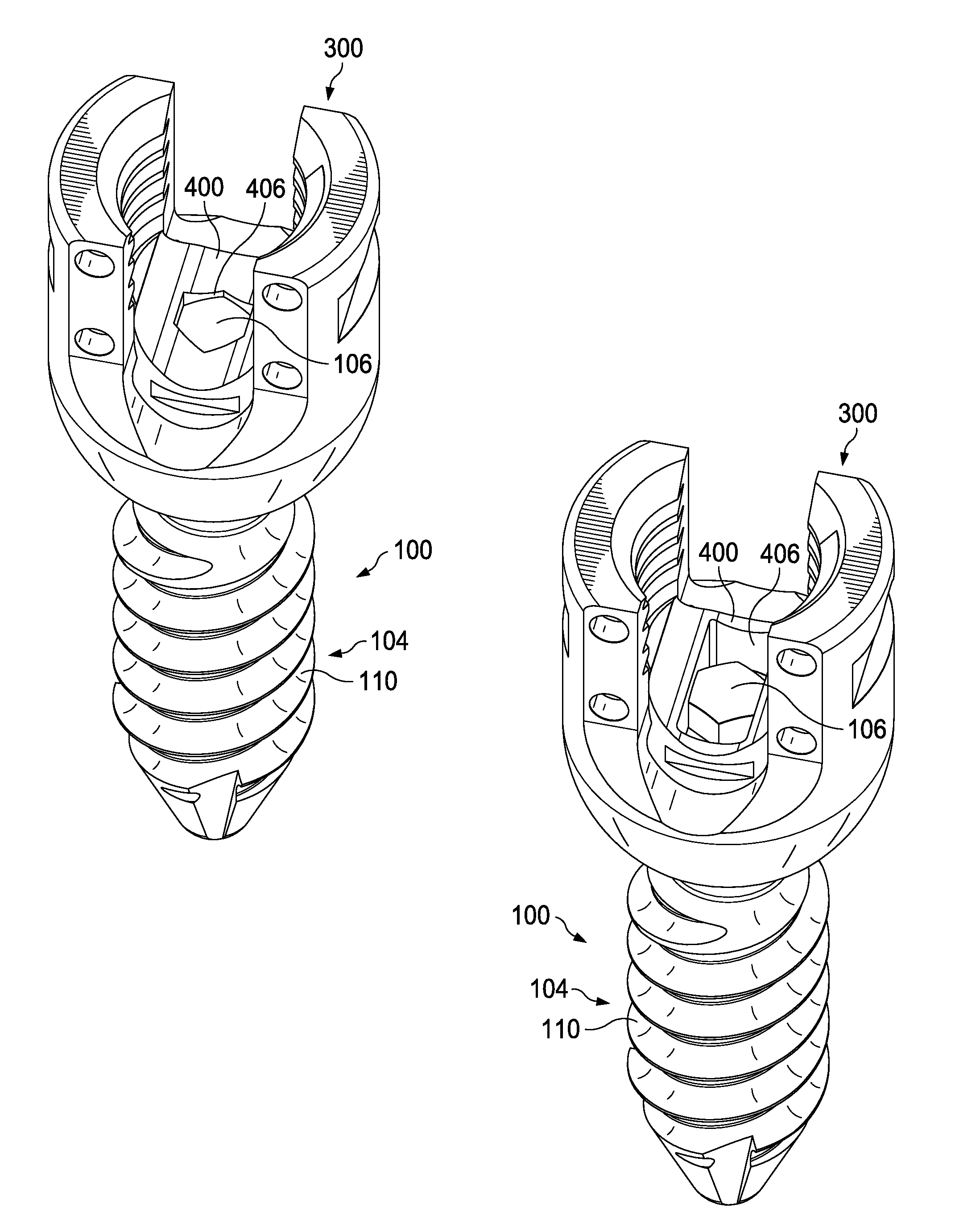
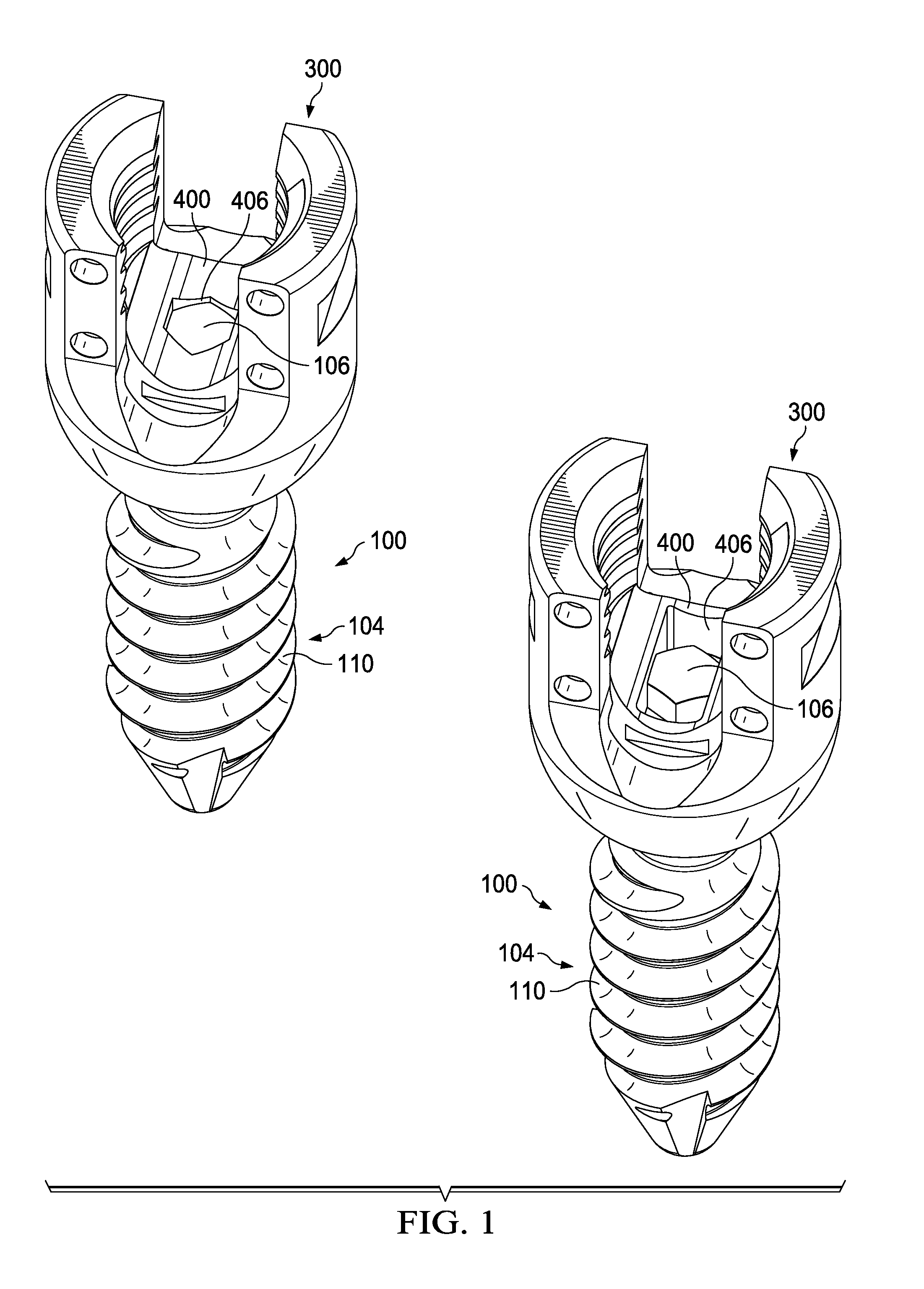
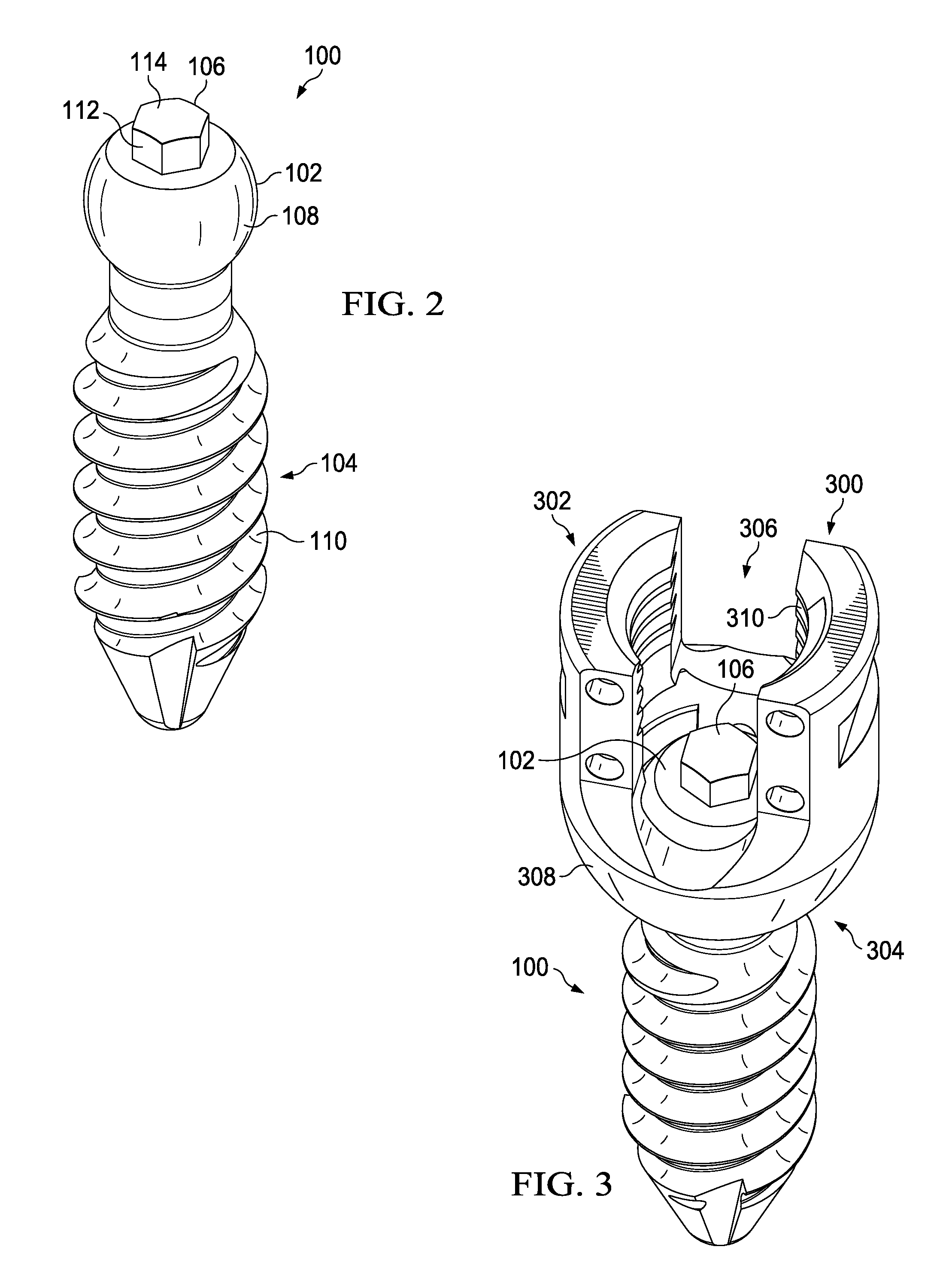
[0028]Referring now to FIG. 1, perspective views of two spinal fixation systems according to exemplary embodiments of the present disclosure are shown. As seen in FIG. 1, the spinal fixation systems according to the present disclosure may comprise bone screw 100, body 300, and pressure cap 400. Bone screw 100 may comprise bone connection element 104, which may comprise external thread 110. External thread 110 may allow bone screw 100 and the spinal fixation system to be secured into a bone. Bone screw 100 may further comprise external protrusion 106 which may be configured to fit with internal recess 406 of pressure cap 400. The two example embodiments illustrated in FIG. 1 show how different spinal fixatio...


PUM


Abstract

The present disclosure relates, in some embodiments, to spinal fixation systems that may comprise a bone screw, a body, and a pressure cap. A bone screw may comprise a head at a proximal end, a bone connection element at a distal end, and an external protrusion on a head of a bone screw. A body may comprise a proximal end, a distal end, a mounting rod receiving channel at a proximal end, and a bone screw head receiving channel at a distal end. A portion of the mounting rod receiving channel may be operable to receive a compression element. A pressure cap may comprise a proximal end, distal end, and an internal recess on a distal end. An internal recess may be configured to mate with an external protrusion of a bone screw so as to limit the movement of a bone screw.

Description

FIELD OF THE DISCLOSURE[0001]The present disclosure relates, in some embodiments, to modular pedicle screws. More specifically, the present disclosure relates, in some embodiments to modular pedicle screws for use in spinal fixation systems.BACKGROUND OF THE DISCLOSURE[0002]Various systems exist for connecting fastener elements (e.g., pedicle screws) to bones for the purposes vertebral fixation. Such systems may use a plurality of bone screws fitted in bodies, wherein a plurality of bodies are aligned using a mounting rod.[0003]A spinal fixation system may comprise several components with various degrees of stability or various degrees of movement between the components themselves or between the components and the bones to which they are affixed. For example, the connection between the bones and the fastener may have a degree of stability. Greater stability may help promote a more secure system and a more secure fixation for multiple segments of the spine. However, overly rigid or i...

Claims


Application Information

Patent Timeline
IPC IPC(8): A61B17/70
CPCA61B17/7035A61B17/7032A61B17/7037
Inventor FANG, SAMUEL
Owner ORTHOFIX US LLC
Why Eureka
Try Eureka