Luminaire controller

Active Publication Date: 2015-04-30
SCHREDER SA
View PDF7 Cites 37 Cited by
  • Summary
  • Abstract
  • Description
  • Claims
  • Application Information

AI Technical Summary

Benefits of technology

[0006]It is therefore an object of the present invention to p

Problems solved by technology

However, such systems are not readily dimmable without the modification, and, in particular

Method used


Image

  • Luminaire controller
  • Luminaire controller
  • Luminaire controller

Examples


Embodiment Construction

[0041]The present invention will be described with respect to particular embodiments and with reference to certain drawings but the invention is not limited thereto. The drawings described are only schematic and are non-limiting. In the drawings, the size of some of the elements may be exaggerated and not drawn on scale for illustrative purposes.

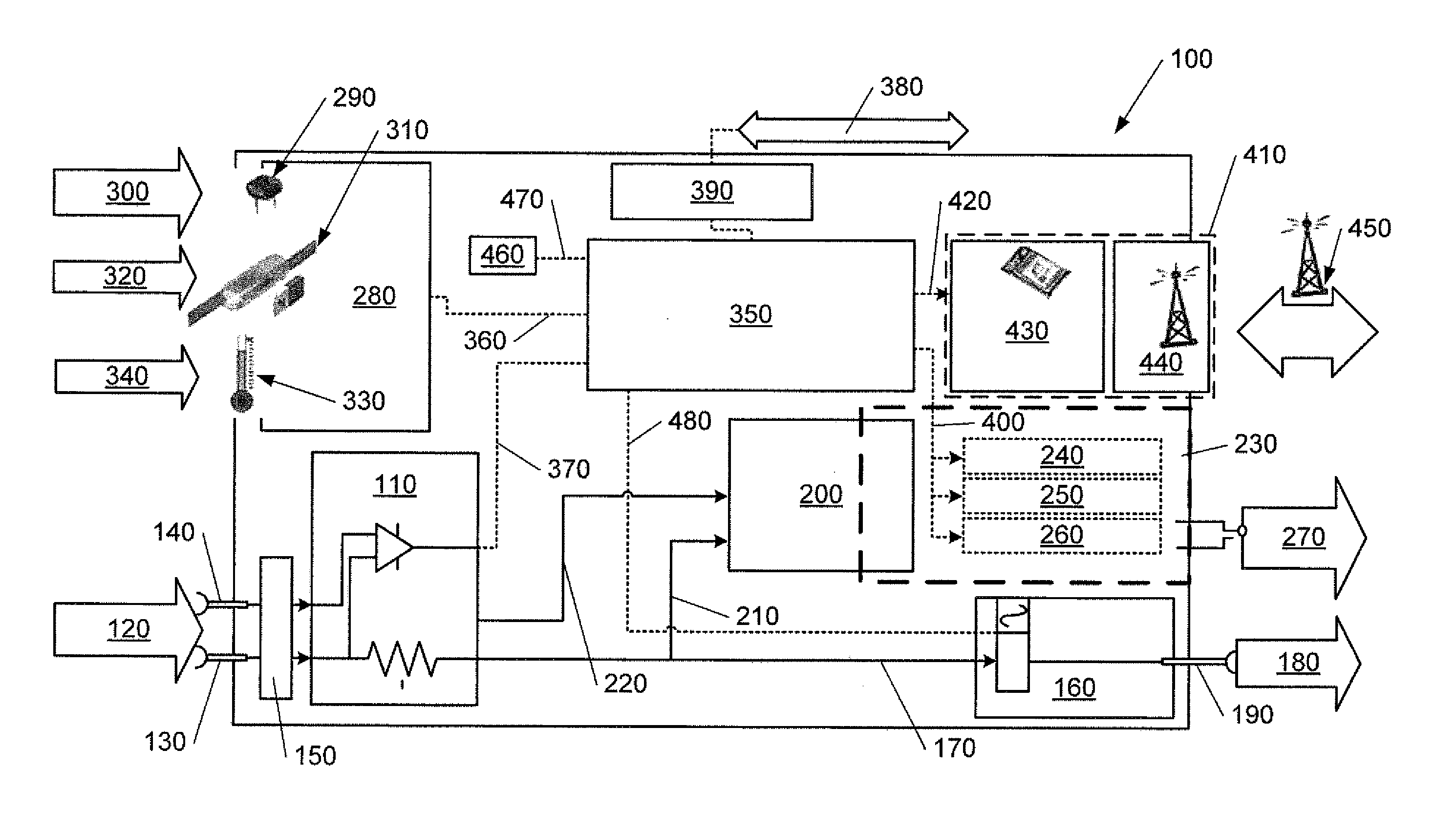
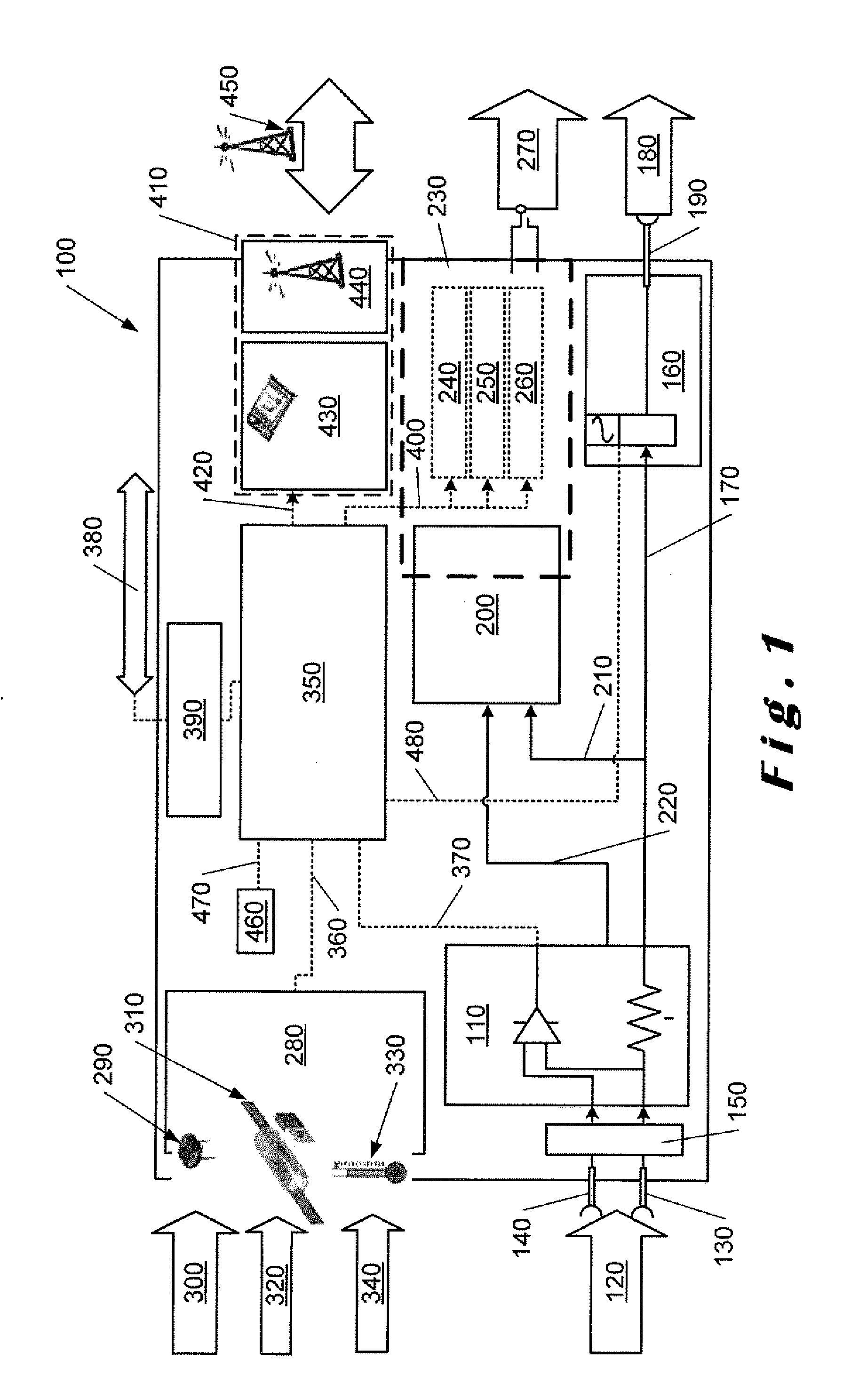
[0042]Luminaires are well-known for lighting large areas and can be used, for example, in street lighting applications. Each luminaire comprises a plurality of light-emitting diode (LED) elements and at least one driver circuit for controlling the operation of the LEDs. The LED driver circuits may be controlled to switch the driver circuit OFF completely during the day if there is a switch provided ahead of the driver circuit. This may be implemented using a switching relay that includes a ZigBee interface switching mains power and has the required level of isolation.

[0043]ZigBee is a trademark of the ZigBee Alliance which provides a specifi...


PUM


Abstract

Described herein is a luminaire controller for a luminaire in which dimming signals can be provided to control the operation of the luminaire. The controller also includes an energy measurement module connected to a mains supply, a sensor module, a power switch, a central processing module and a ZigBee transceiver module. The controller, in addition to providing dimming signals in accordance with ambient lighting conditions sensed by a photocell in the sensor module provides efficient energy metering. In one embodiment, the luminaire controller is directly mountable on a luminaire which is to for control thereof.

Description

FIELD OF THE INVENTION[0001]The present invention relates to luminaire controllers, and is more particularly, although not exclusively, concerned with luminaire controllers having dimming capability.BACKGROUND TO THE INVENTION[0002]It is known to provide high intensity dimmable light-emitting diode (LED) luminaires for use in both indoor and outdoor spaces. On such LED luminaire is described in US-A-2012 / 0033400 for use as emergency ballast for car parks. The luminaire can have either a fixed output or a dimmable output and incorporates a movement sensor which can be used to change the illumination status of the luminaire. In addition, different turn-off schemes are described including a progressive turn-off with soft transitions between lighting levels.[0003]In addition, it is known to use a light sensor in luminaires in a night mode operation. One such luminaire is described in GB-A-2459180 where a light sensor is incorporated into a luminaire system having a movement sensor and a...

Claims


Application Information

Patent Timeline
IPC IPC(8): H05B33/08F21V23/00H05B37/02H05B44/00
CPCH05B33/0854F21V23/007H05B37/0227H05B37/0218H05B47/18H05B47/11H05B47/19F21V23/0464F21W2131/103Y02B20/40H05B45/18F21V23/008H05B47/105H05B45/12
Inventor SCHRODER, HELMUTBRAND, DANIEL
Owner SCHREDER SA
Why Eureka
Try Eureka