Coaxial cable and connector with capacitive coupling

a technology of capacitive coupling and coaxial cable, which is applied in the direction of multiple-port network, waveguide-type devices, coupling device connections, etc., can solve problems such as degrading the electrical performance of an entire rf system

Active Publication Date: 2015-04-30
COMMSCOPE TECH LLC
View PDF4 Cites 27 Cited by
  • Summary
  • Abstract
  • Description
  • Claims
  • Application Information

AI Technical Summary

Problems solved by technology

PIM can be an important interconnection quality characteristic, as PIM generated by a single low quality interconnection may degrade the electrical performance of an entire RF system.

Method used


Image

  • Coaxial cable and connector with capacitive coupling
  • Coaxial cable and connector with capacitive coupling
  • Coaxial cable and connector with capacitive coupling

Examples


Embodiment Construction

[0025]The present invention is described with reference to the accompanying drawings, in which certain embodiments of the invention are shown. This invention may, however, be embodied in many different forms and should not be construed as limited to the embodiments that are pictured and described herein; rather, these embodiments are provided so that this disclosure will be thorough and complete, and will fully convey the scope of the invention to those skilled in the art. It will also be appreciated that the embodiments disclosed herein can be combined in any way and / or combination to provide many additional embodiments.

[0026]Unless otherwise defined, all technical and scientific terms that are used in this disclosure have the same meaning as commonly understood by one of ordinary skill in the art to which this invention belongs. The terminology used in the above description is for the purpose of describing particular embodiments only and is not intended to be limiting of the inven...


PUM


Abstract

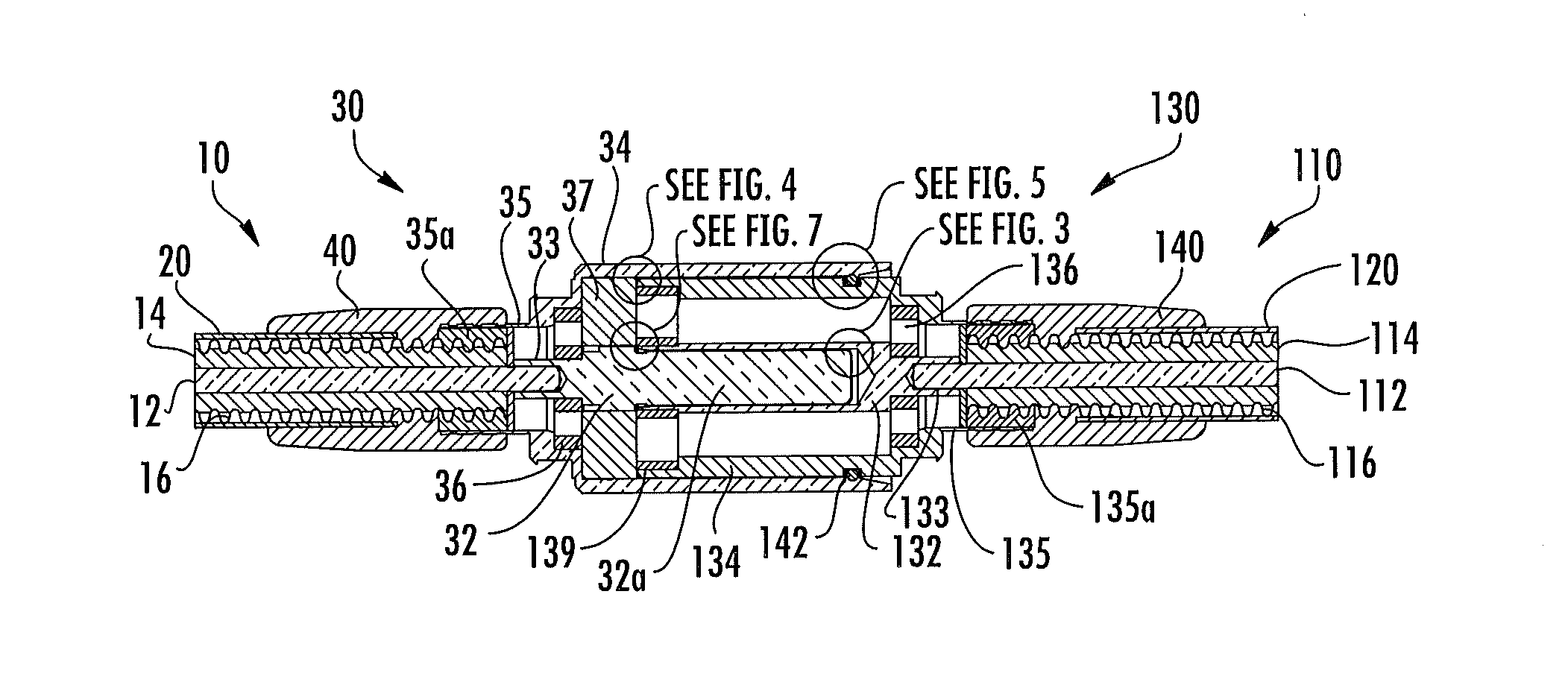
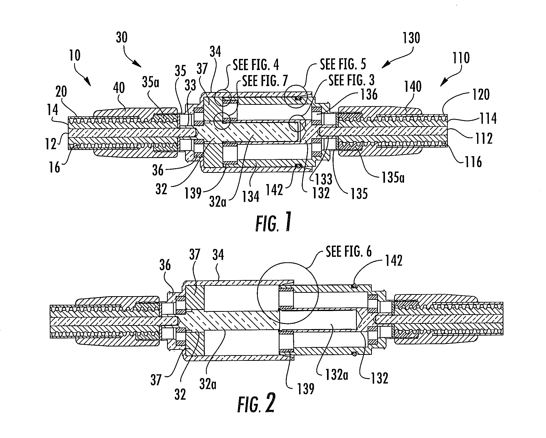
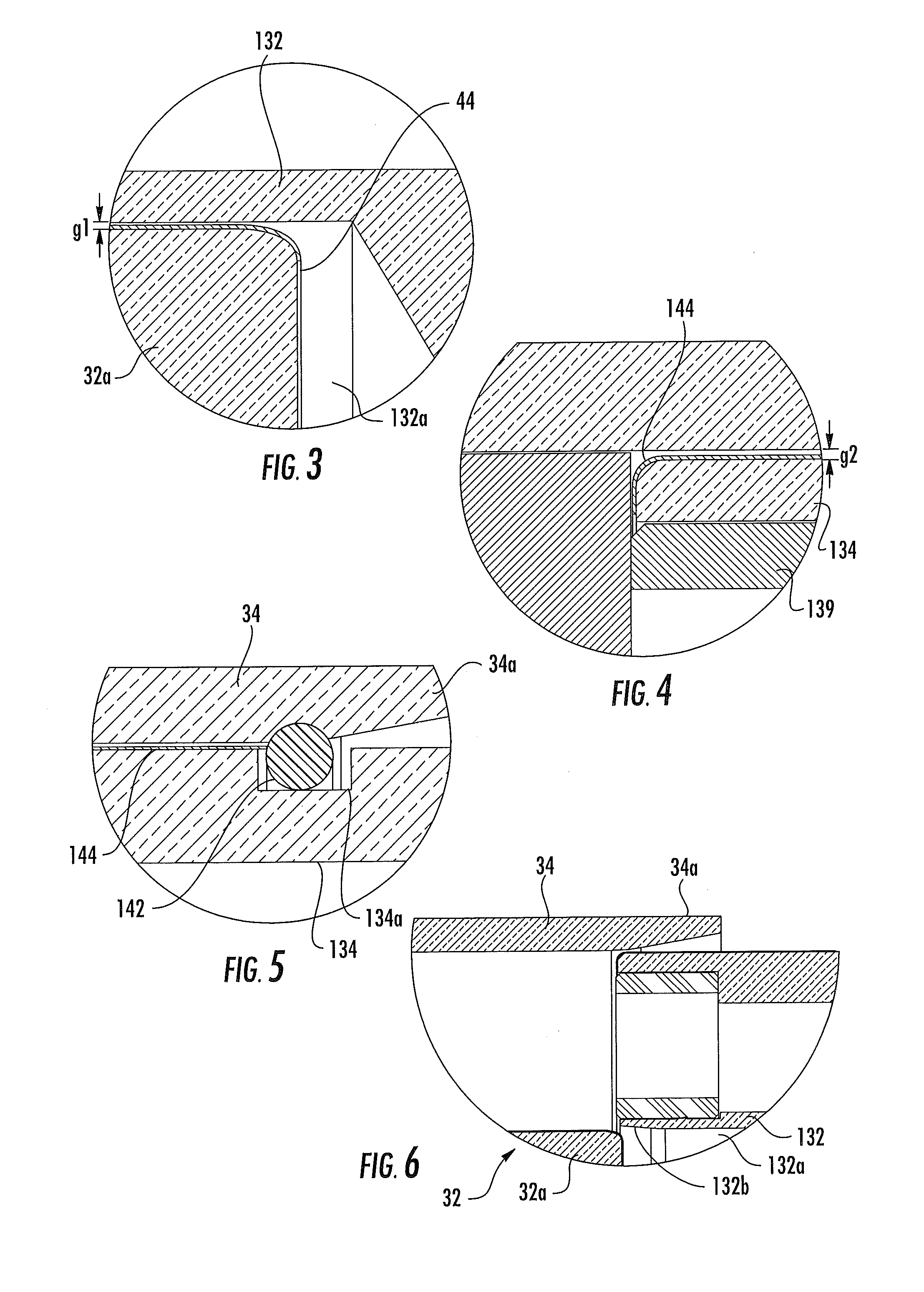
A coaxial connector junction includes first and second coaxial connectors. The first coaxial connector includes: a first central conductor extension; a first outer conductor extension spaced apart from and circumferentially surrounding the first central conductor extension; and a first dielectric spacer interposed between the first central conductor extension and the first outer conductor extension. The second coaxial connector includes: a second central conductor extension; a second outer conductor extension spaced apart from and circumferentially surrounding the second central conductor extension; and a second dielectric spacer interposed between the second central conductor extension and the second outer conductor extension. Each of the central conductor extensions and the outer conductor extensions has circular symmetry about the longitudinal axis, such that electrical properties of the engaged first and second coaxial connectors are substantially the same irrespective of the relative orientations of the first and second coaxial connectors about the longitudinal axis.

Description

RELATED APPLICATION[0001]The present application claims the benefit of and priority from U.S. Provisional Patent Application No. 61 / 895,113, filed Oct. 24, 2013. The present application is a continuation-in part of, and claims priority from and the benefit of, U.S. patent application Ser. No. 14 / 102,042, filed Dec. 10, 2013. The disclosures of both of these documents are hereby incorporated herein in their entirety.FIELD OF THE INVENTION[0002]The present invention is directed generally to electrical cable connectors, and more particularly to coaxial connectors for electrical cable.BACKGROUND OF THE INVENTION[0003]Coaxial cables are commonly utilized in RF communications systems. A typical coaxial cable includes an inner conductor, an outer conductor, a dielectric layer that separates the inner and outer conductors, and a jacket that covers the outer conductor. Coaxial cable connectors may be applied to terminate coaxial cables, for example, in communication systems requiring a high ...

Claims


Application Information

Patent Timeline
Patent Type & Authority Applications(United States)
IPC IPC(8): H01R9/05H01R13/6597H01R13/52
CPCH01R9/0503H01R13/6597H01R13/5219H02J50/05
Inventor PAYNTER, JEFFREY D.VACCARO, RONALD A.
Owner COMMSCOPE TECH LLC
Why Eureka
Try Eureka