Semiconductor light-emitting device

Inactive Publication Date: 2015-05-14
CITIZEN WATCH CO LTD +1
View PDF14 Cites 4 Cited by
  • Summary
  • Abstract
  • Description
  • Claims
  • Application Information

AI Technical Summary

Benefits of technology

[0020]The semiconductor light-emitting device described above is configured by fluorescent semiconductor light-emitting elements of which an outer surface is coated with a resin containing a fluorescent material, which makes it possible to coat each semiconductor light-emitting element with a resin containing a different fluorescent material. Thus, it is possible to provide a semiconductor light-emitting device which has excellent color rendering characteristics and which enables selection of a variety of emission colors in accordance with the use of the device.
[0021]In addition, by facing each other and directly connecting the neighboring electrodes of fluorescent semiconductor light-emitting elements, the neighboring fluorescent semiconductor light-emitting elements overlapping in a depthwise direction, which leads to a two-layer configuration with an upper layer and a lower layer. As a result, a semic

Problems solved by technology

However, with such conventional technologies, it has not been possible to sufficiently satisfy demand for excellent color rendering characteristics required for light-emitting

Method used


Image

  • Semiconductor light-emitting device
  • Semiconductor light-emitting device
  • Semiconductor light-emitting device

Examples


Example

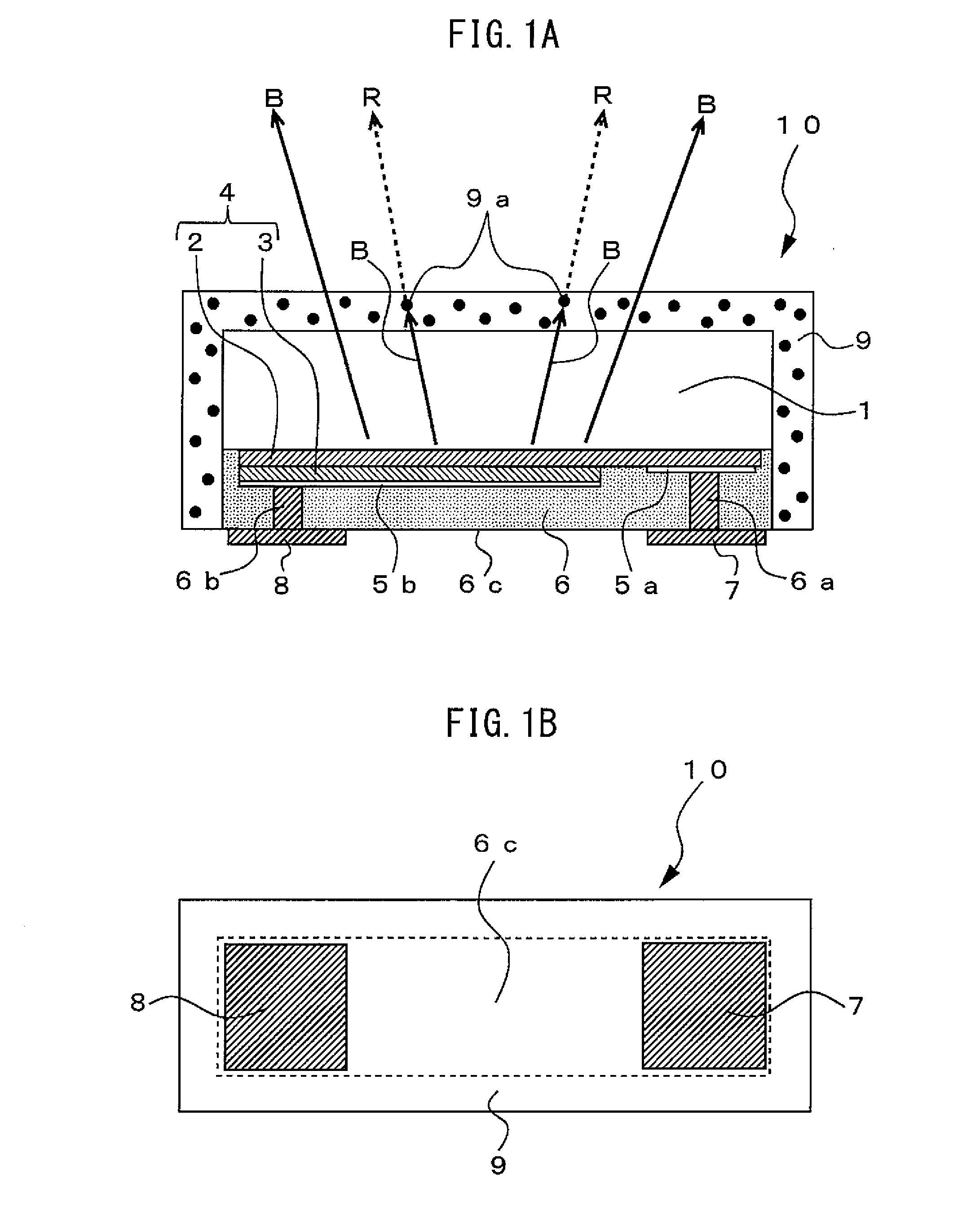
[0076]Next, a semiconductor light-emitting device of the second exemplary embodiment will be described using FIG. 8. The basic configuration of the second exemplary embodiment is the same as that of the first exemplary embodiment, and only the type of the fluorescent material 9a contained in the fluorescent resin 9 of the fluorescent LEDs 10 and the inclusion of the sealing material 26 which seals the LED assemblies are different. Thus, an overlapping description of the configuration will be omitted by giving the same number to the same component, and a description with a focus on the operation of the semiconductor light-emitting device and the wavelength distribution of the emitted light will be made. In the second exemplary embodiment, the LED elements 4 of the fluorescent LEDs 10 are blue LEDs as is the case in the first exemplary embodiment, and the fluorescent material 9a (see FIG. 1A) contained in the fluorescent resin 9 coating the outer surface of the fluorescent LEDs 10 is ...

Example

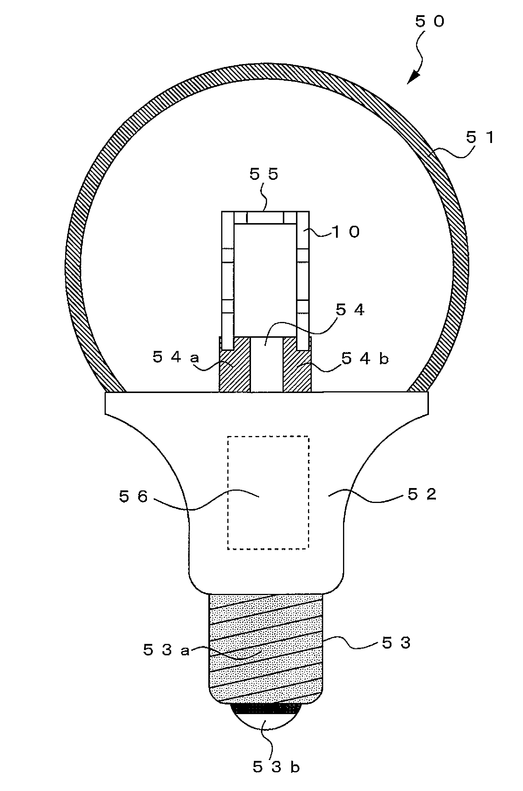
[0086]Next, a semiconductor light-emitting device of the third exemplary embodiment will be described using FIG. 11. In FIG. 11, the reference sign 50 indicates a semiconductor light-emitting device of the third exemplary embodiment. The semiconductor light-emitting device 50 includes a light-bulb-type housing, a substantially spherical resin cover 51 which seals a LED assembly, a support unit 52 made of insulating material, and a connection unit 53 for inputting electric power from outside. A electrode unit 54 made of an insulating substrate is disposed substantially in the center of the support unit 52, and a pair of electrodes 54a and 54b is formed on the electrode unit 54.

[0087]An LED assembly 55 in which the fluorescent LEDs 10 are connected in series in a substantially squared ‘U’ shape is disposed at an upper portion, on the drawing, of the electrode unit 54. The electrode unit 54 is attached vertically in relation to the support unit 52, so the LED assembly 55 is also suppor...


PUM

PropertyMeasurementUnit
Fluorescenceaaaaaaaaaa

Abstract

Provided is a compact and high-luminance semiconductor light-emitting device which has excellent color rendering characteristics and which enables arbitrary selection of emission color depending on the use of the device. The semiconductor light-emitting device includes a light-emitting element assembly configured by a plurality of fluorescent semiconductor light-emitting elements each of which has external connection electrodes respectively connected to an n-type semiconductor layer and a p-type semiconductor layer, wherein at least an outer surface other than the external connection electrodes of each of the fluorescent semiconductor light-emitting elements is coated with a resin containing a fluorescent material. The light-emitting element assembly is configured such that the external connection electrodes of the fluorescent semiconductor light-emitting elements are directly connected in series using solder.

Description

CROSS REFERENCE TO RELATED APPLICATION[0001]This application is a new U.S. patent application that claims benefit of JP 2013-206057, filed on Oct. 1, 2013. The entire content of JP 2013-206057 is hereby incorporated by reference.TECHNICAL FIELD[0002]The present invention relates to a semiconductor light-emitting device in which multiple semiconductor light-emitting elements are connected together, and which is used as a variety of light sources.BACKGROUND[0003]Light-emitting diodes (hereafter abbreviated as LEDs), which are compound semiconductors, have been widely utilized as light-emitting devices, taking advantage of characteristics such as long operating life and compact size. Furthermore, as a result of the development of LEDs which emit blue light using, for example, gallium nitride based compound semiconductors, the commercialization of white light and pseudo-white light-emitting devices has advanced, and high luminance and high output light-emitting devices, for which LED he...

Claims


Application Information

Patent Timeline
IPC IPC(8): H01L25/075H01L33/62H01L33/54H01L33/50H01L33/48
CPCH01L25/0753H01L33/504H01L33/62H01L33/486H01L33/54H01L33/507F21K9/232F21V3/062F21Y2115/10H01L2924/0002H01L2924/00
Inventor IINO, TAKASHI
Owner CITIZEN WATCH CO LTD
Why Eureka
Try Eureka