Module board

Active Publication Date: 2014-07-03
MURATA MFG CO LTD
View PDF36 Cites 9 Cited by
  • Summary
  • Abstract
  • Description
  • Claims
  • Application Information

AI Technical Summary

Benefits of technology

[0031]In the above arrangement, since the multiple electronic components are mounted also on the other face of the substrate, it is possible to achieve the higher mounting density of the electronic components to reduce the size of the module board.
[0032]With the above arrangements, it is possible to suppress the depression of the top face of the insulating resin near the center of the subs

Problems solved by technology

When the thickness of the insulating resin is made small near the center of the substrate, there is a problem in that it is difficult to flatten the insulating resin to cause the accumulation of flux resin or the air entrainment, etc. in the mounting on a m

Method used


Image

  • Module board
  • Module board
  • Module board

Examples


Example

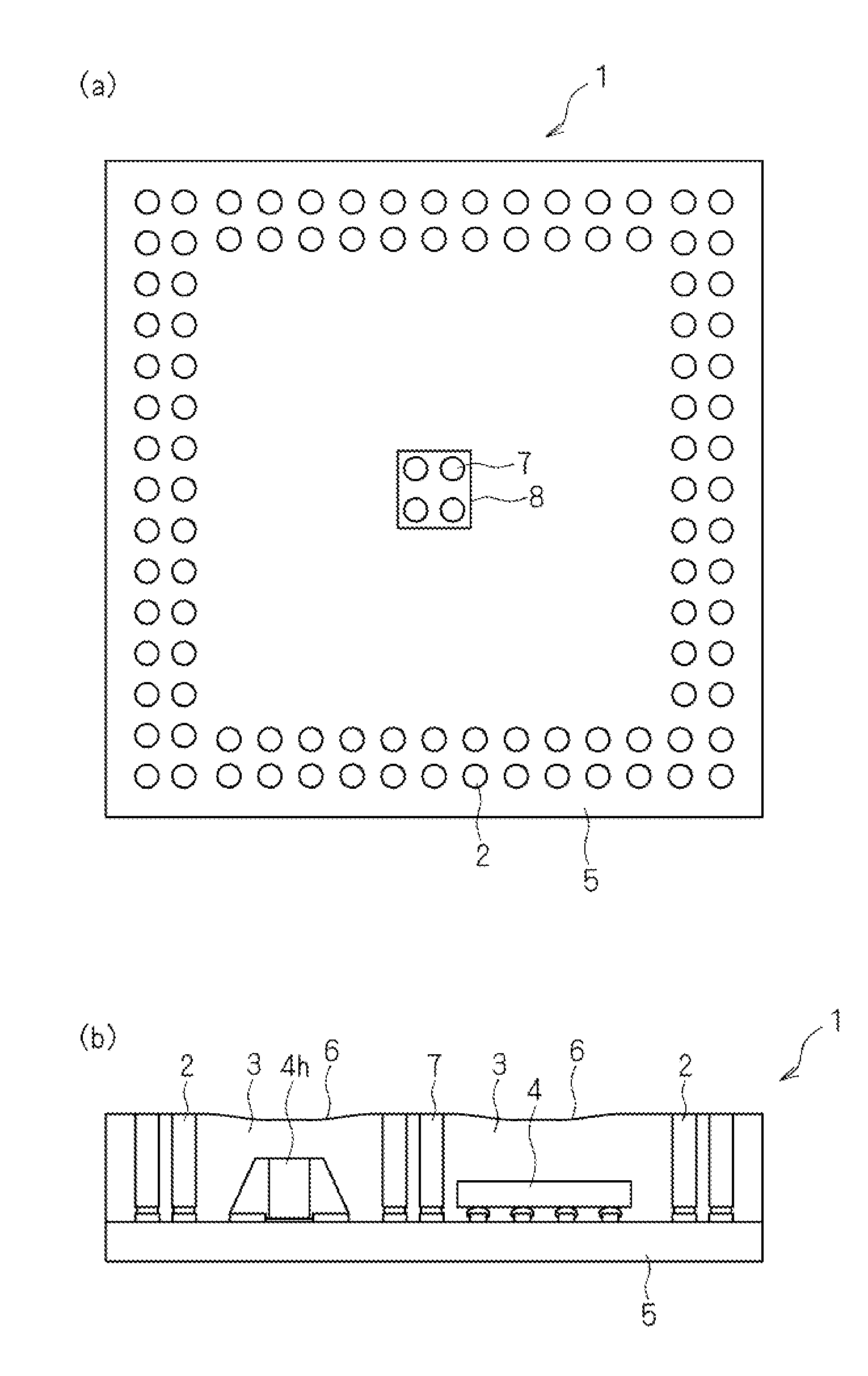
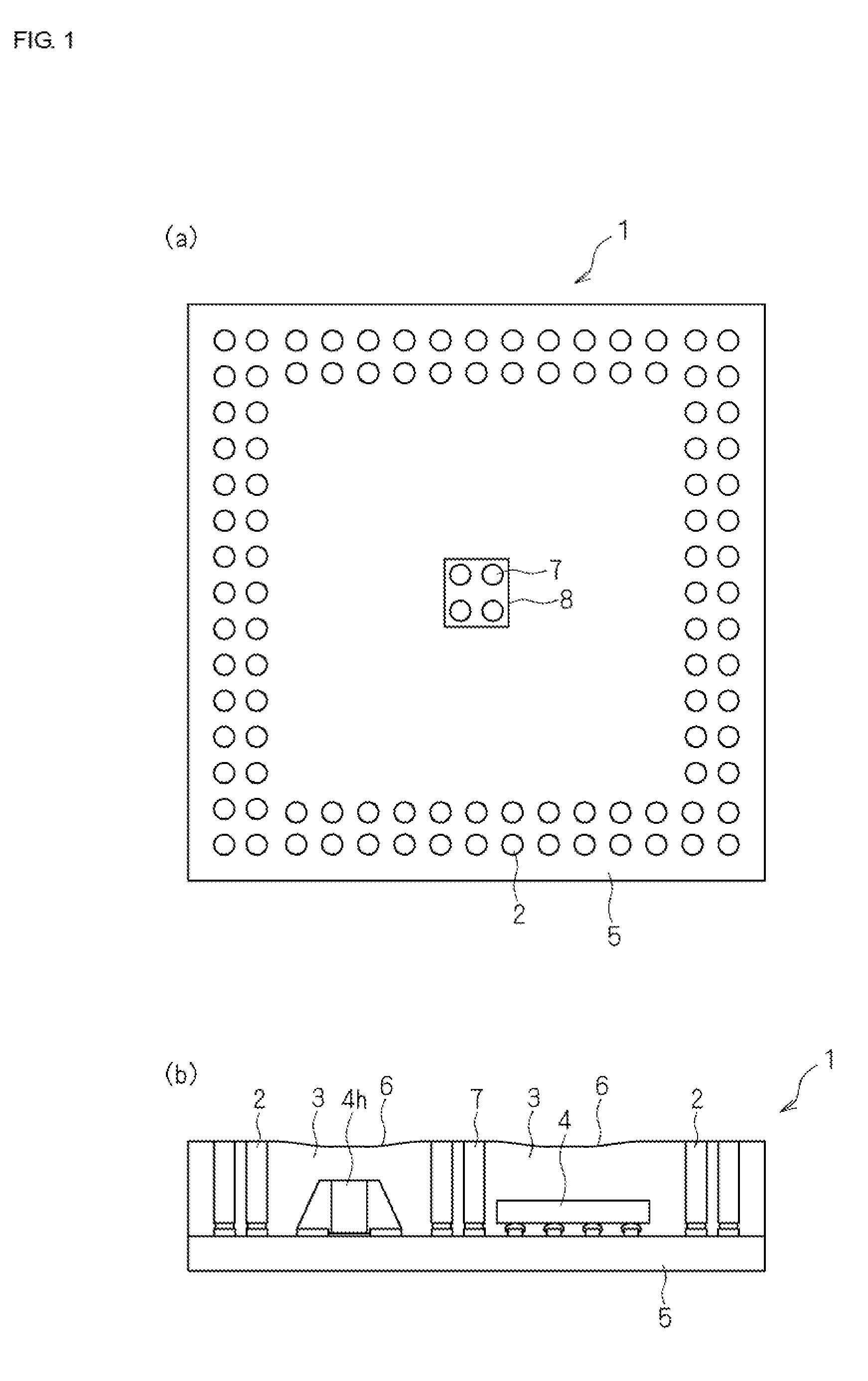
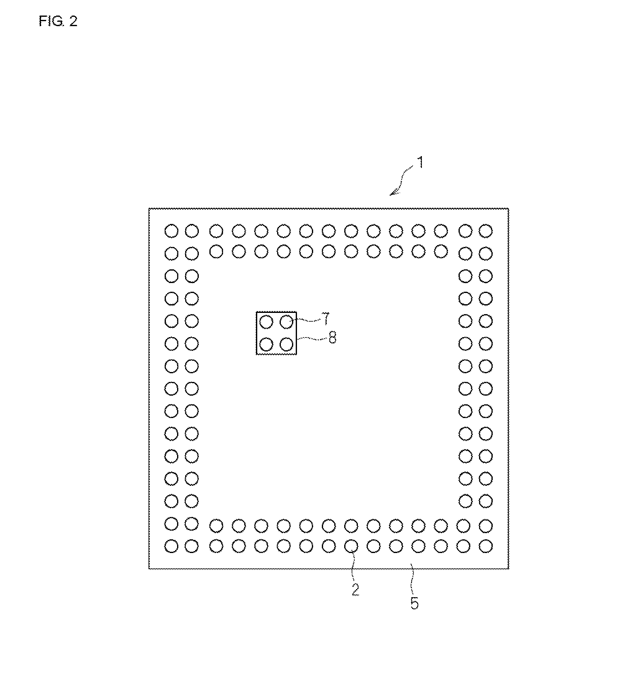
[0040]Embodiments of the present invention will herein be described in detail with reference to the attached drawings. FIG. 7 includes a plan view and a cross-sectional view illustrating an arrangement of a module board in the related art. FIG. 7(a) is a plan view of a module board 1 in the related art. In the module board 1, multiple columnar connection terminals 2 are arranged on a peripheral area of a substrate 5. FIG. 7(b) is a cross-sectional view of the module board 1 in the related art. Referring to FIG. 7(b), the heights of the multiple columnar connection terminals 2 from one face of the substrate 5 are made greater than those of electronic components (surface mount devices (SMDs)) 4 from the one face of the substrate 5.

[0041]When the electronic components 4 that are mounted are sealed with insulating resin 3, a top face 6 of the insulating resin 3 is kept flat near the multiple columnar connection terminals 2 arranged on the peripheral area of the substrate 5. However, the...


PUM


Abstract

To provide a module board capable of suppressing depression of a top face of insulating resin near the center of a substrate by arranging multiple columnar connection terminals not only on a peripheral area of the substrate but also between multiple electronic components that are mounted. Multiple electronic components 4 and 4h are mounted on one face of a substrate 5 and the multiple electronic components 4 and 4h are sealed with insulating resin 3. Multiple columnar connection terminals 2 and 7 are arranged on a peripheral area of the substrate 5 and in one or more small areas 8 on the substrate 5, respectively. The one or more small areas 8 are set at positions on the substrate 5, which is not on the peripheral area of the substrate 5 and on which the multiple electronic components 4 and 4h are not mounted.

Description

BACKGROUND OF THE INVENTION[0001]1. Field of the Invention[0002]The present invention relates to a module board in which multiple electronic components are mounted on one face of a substrate and the multiple electronic components are sealed with an insulating resin. In particular, the present invention relates to a module board in which multiple columnar connection terminals are arranged not only on a peripheral area of a substrate but also between the multiple electronic components that are mounted.[0003]2. Description of the Related Art[0004]Many circuit boards have hitherto been developed in which multiple columnar posts are formed on the peripheral areas of substrates and the columnar posts are exposed from the top face of an insulating resin with which inner connection electrodes are sealed to use the columnar posts as outer electrodes. For example, Patent Document 1 discloses a method of manufacturing a semiconductor integrated circuit device in which columnar conductive posts...

Claims


Application Information

Patent Timeline
IPC IPC(8): H05K1/02H05K1/18
CPCH05K1/185H05K1/0296H01L25/04H01L25/18H01L23/3121H01L21/561H01L21/565H01L23/49811H01L24/16H01L2224/81815H01L2224/97H01L2224/16227H01L2224/81192H01L2224/16225H01L2924/12042H01L2224/05573H01L2224/05568H01L2224/0558H01L25/16H01L2225/06548H01L2924/00014H01L2224/81H01L2924/00H01L2224/05611H01L2224/05639H01L2224/05644H01L2224/05655H01L23/52H01L23/00H01L23/12H01L23/48
Inventor MIZUSHIRO, MASAAKI
Owner MURATA MFG CO LTD
Why Eureka
Try Eureka