

Operation interface device and operation interface method
a technology of operation interface and operation interface, which is applied in the direction of instruments, cathode-ray tube indicators, computing, etc., can solve the problem of bothersome display of cursor, and achieve the effect of improving the operability of the touch panel and the remote operation devi
- Summary
- Abstract
- Description
- Claims
- Application Information
AI Technical Summary
Benefits of technology
Problems solved by technology
Method used
Image

Examples
embodiment 1
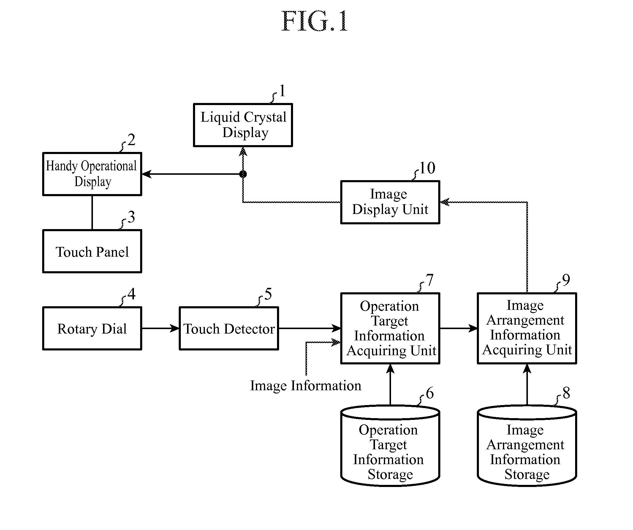
[0042]FIG. 1 is a block diagram showing a configuration of an operation interface device of an embodiment 1 in accordance with the present invention.
[0043]In FIG. 1, a liquid crystal display 1, which is installed at a position beyond the reach of an operator (such as in a dashboard of a vehicle when the operation interface device is mounted as an onboard operation device), is a large-sized display that displays an image including a map of navigation or audio information. Incidentally, the liquid crystal display 1 constitutes a first display.
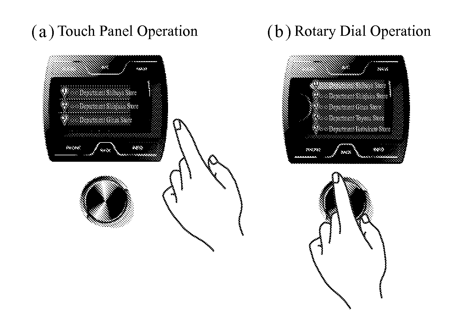
[0044]A handy operational display 2, which is placed within reach of an operator (mounted on the console or steering wheel of the vehicle when the operation interface device is mounted as an onboard operation device, for example), is a display that displays roughly the same image as the image displayed on the display 1 (part of an image displayed on the liquid crystal display 1). Incidentally, the handy operational display 2 constitutes a second ...
embodiment 2
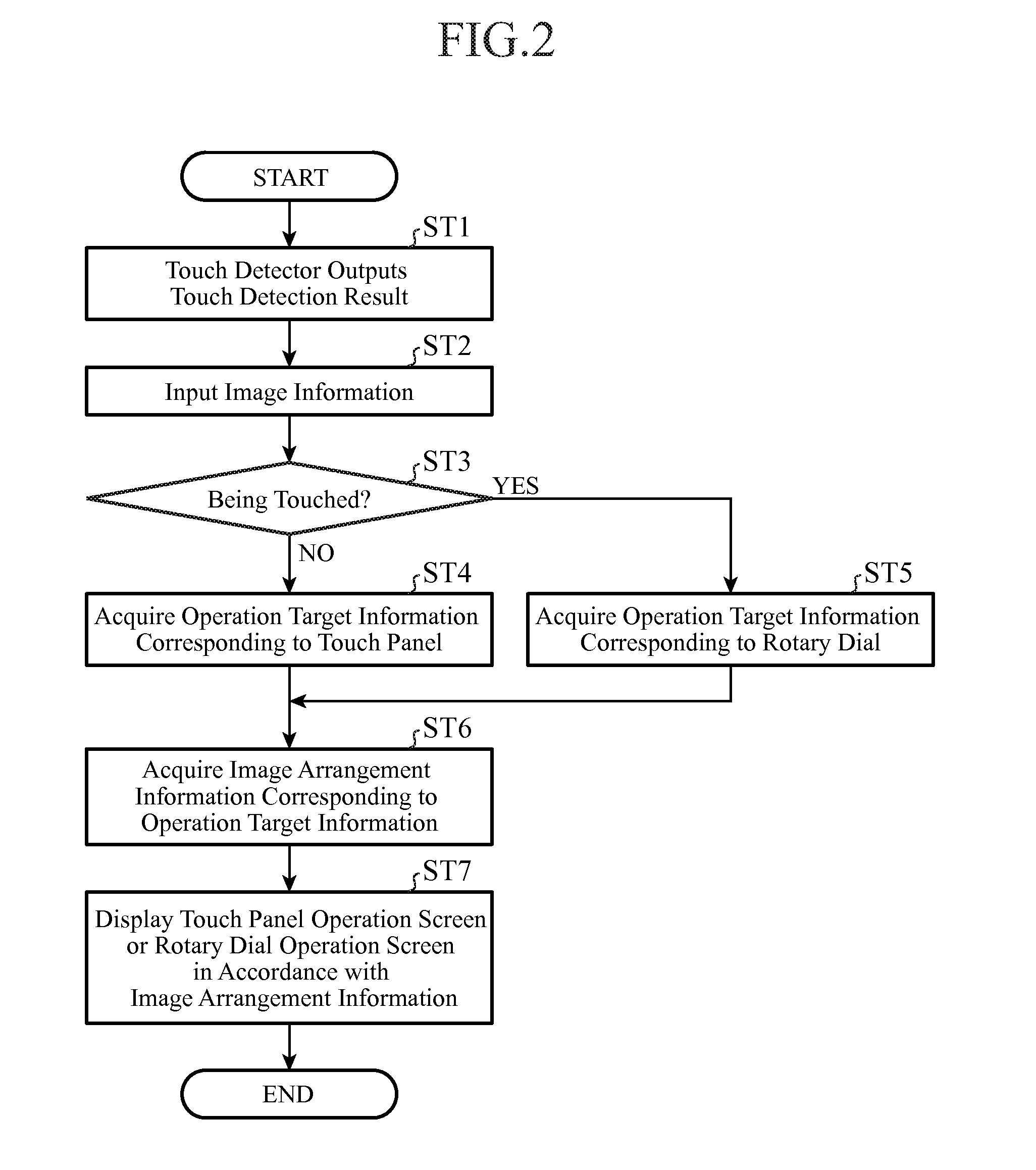
[0140]Although the foregoing embodiment 1 shows the configuration in which the touch detector 5 detects the touch of the operator to the rotary dial 4 by detecting a current flowing through the electric conductor, a configuration is also possible in which even an operator does not touch the rotary dial 4, the touch detector 5 outputs a detection result indicating that the operator touches the rotary dial 4 if the rotary dial 4 and the operator are close enough to each other, that is, the distance between them is not greater than a prescribed value.
[0141]For example, when the touch detector 5 is comprised of a capacitance touch sensor, if the distance between the rotary dial 4 and the operator becomes not greater than a prescribed value, the capacitance of the touch sensor exceeds a prescribed value, thereby enabling detecting the approach of the operator to the rotary dial 4.
[0142]Since the processing contents on and after the processing of the operation target information acquiring...
embodiment 3
[0144]FIG. 23 is a block diagram showing a configuration of an operation interface device of an embodiment 3 in accordance with the present invention. In FIG. 23, since the same reference numerals as those of FIG. 1 designates the same or like components, their description will be omitted.
[0145]A remote control 11 is a remote operation device that accepts a remote operation.
[0146]In the present embodiment 3, an example will be described which comprises a plurality of remote operation devices (the rotary dial 4 and the remote control 11). A combination of the plurality of remote operation devices, however, is not limited to a combination of the rotary dial 4 and the remote control 11, but a combination of three or more remote operation devices is possible.
[0147]Incidentally, the touch detector 5 is provided to each of the remote operation devices.
[0148]A detection device identifying unit 12, which is comprised of a semiconductor integrated circuit incorporating a CPU or of a single-c...
PUM
 Abstract
Description
Claims
Application Information