Quick Disconnect Method and Apparatus for Utility Power Distribution Systems

a technology of utility power distribution system and quick disconnect method, which is applied in the directions of coupling device connection, coupling/disconnecting parts arrangement, and mechanical tension relived arrangement, etc. it can solve the problems of insufficiently addressing the need for a safe, effective, reliable, low cost system, and none of the known prior art solutions are as effective at interfacing

Active Publication Date: 2015-05-14
SKYSIGHT TECH
View PDF1 Cites 9 Cited by
  • Summary
  • Abstract
  • Description
  • Claims
  • Application Information

AI Technical Summary

Benefits of technology

[0025]The proposed quick release connector of the present invention independently detects unexpected mechanical loads on power distribution lines. The present invention is useful for any above ground electrical line. Thus, although the words “power line” or “power distribution line” are used herein, the present invention is useful for so called utility lines, service lines, or another above ground power transmission line. When the quick release connector of the present invention is used, as line tension reaches a predetermined release level, the line is released and falls to the ground such that the components of the quick release connector remain attached to their respective power line segments so that the components may be easily reached for line reattachment. Basically, one component remains on line near pole and other component is on the ground

Problems solved by technology

However, none of the known prior art solutions is as effective at interfacing with the existing distribution system to reduce excess loading forces on a utility pole, thereby preventing damage to the pole and power line and allowing rapid power restoration.
The prior art, however, has failed to fully address the need for a safe, effective, reliable, low cost, system for releasing a power line from a utility pole prior to the power distribution system suffering damage and / or prior to live power lines being pulled to ground level.

Method used


Image

  • Quick Disconnect Method and Apparatus for Utility Power Distribution Systems
  • Quick Disconnect Method and Apparatus for Utility Power Distribution Systems
  • Quick Disconnect Method and Apparatus for Utility Power Distribution Systems

Examples


Embodiment Construction

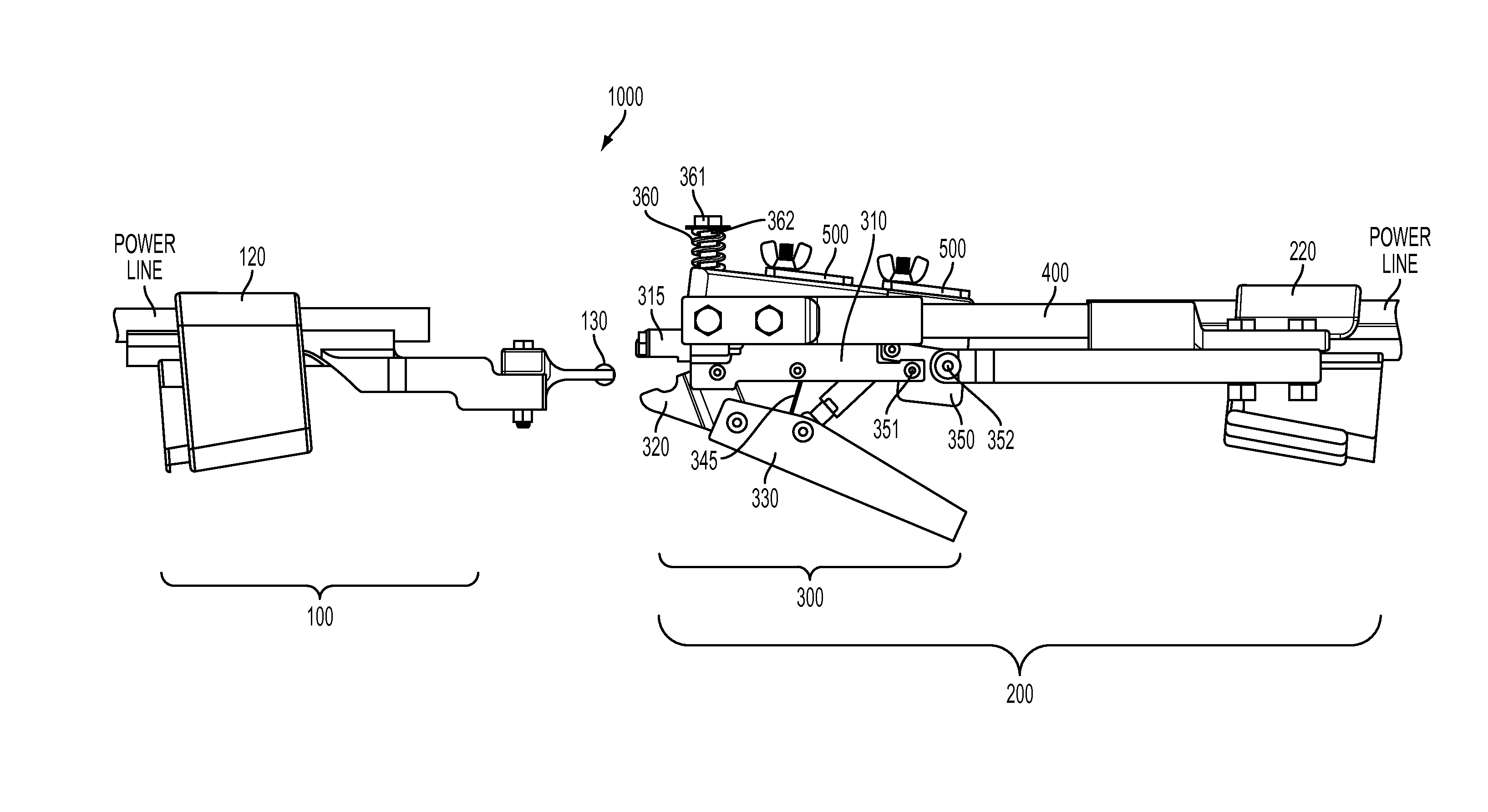
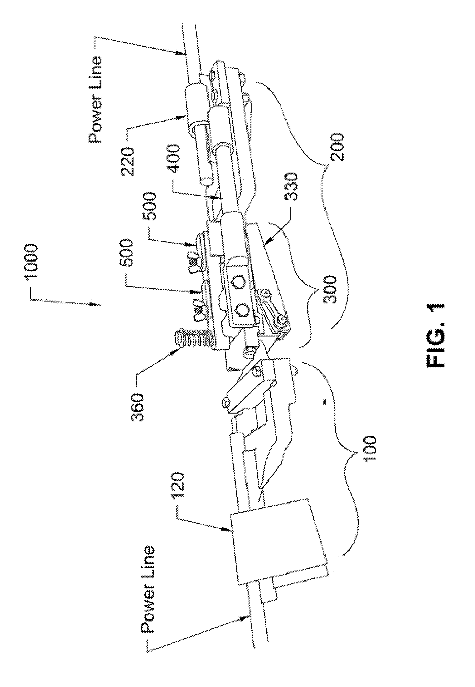
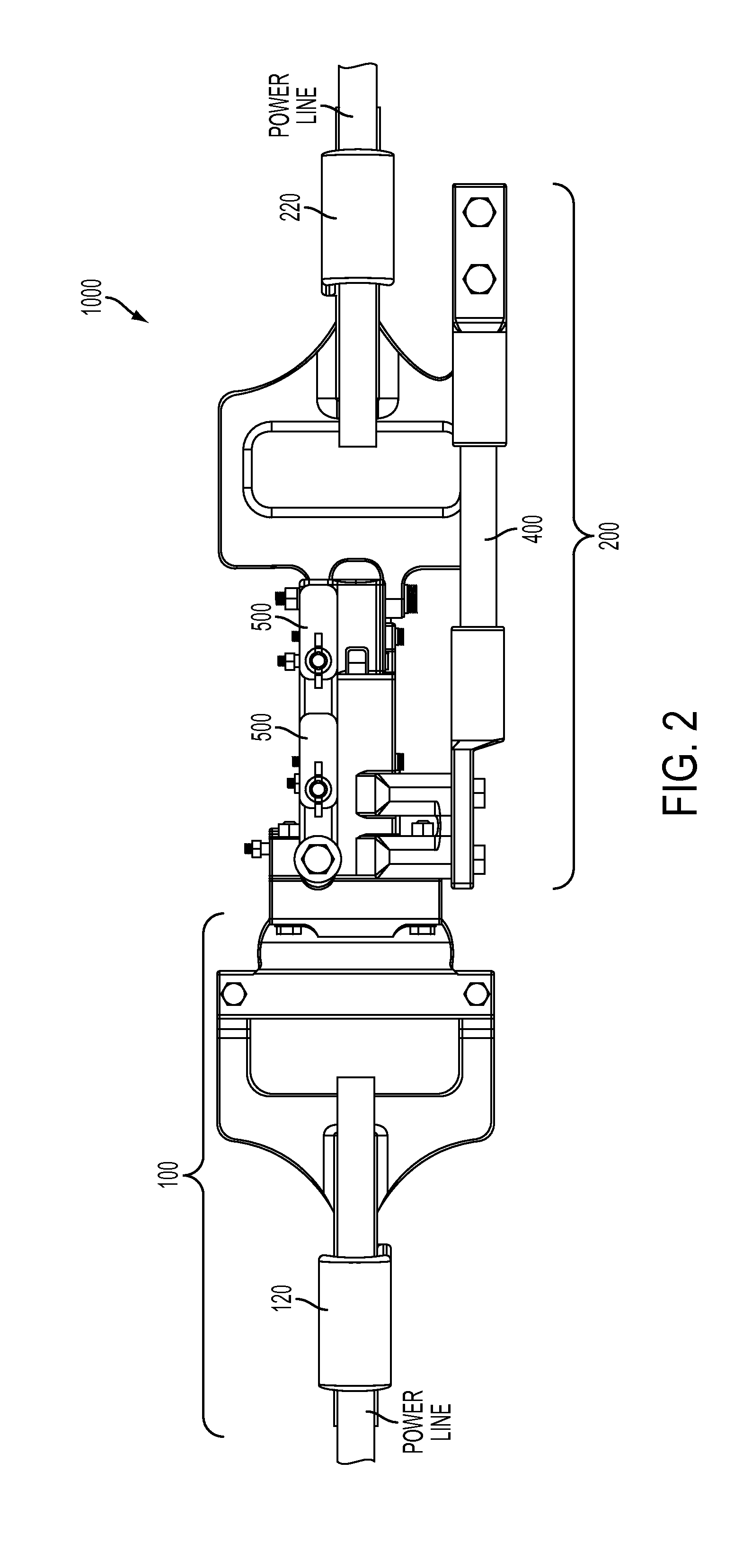
[0044]The present invention will be discussed hereinafter in detail in terms of the preferred embodiment according to the present invention with reference to the accompanying drawings. In the following description, numerous specific details are set forth in order to provide a thorough understanding of the present invention. It will be obvious, however, to those skilled in the art that the present invention may be practiced without these specific details. In other instances, well-known structures are not shown in detail in order to avoid unnecessary obscuring of the present invention.

[0045]The following detailed description is merely exemplary in nature and is not intended to limit the described embodiments or the application and uses of the described embodiments. As used herein, the word “exemplary” or “illustrative” means “serving as an example, instance, or illustration.” Any implementation described herein as “exemplary” or “illustrative” is not necessarily to be construed as pre...


PUM

PropertyMeasurementUnit
angleaaaaaaaaaa
forceaaaaaaaaaa
forceaaaaaaaaaa

Abstract

A quick release connector for tensioned power lines, the connector comprising: a first component, said first component attached to a power line segment; and a second component attached to a second generally collinear power line segment, said second component comprising a locking clamp mechanism that selectively clamps the first component and automatically releases upon the application of a longitudinal force of predetermined magnitude along the clamp.

Description

BACKGROUND[0001]1. Field of the Art[0002]The present invention relates generally to a utility power line safety and maintenance device. More specifically, but without limitation, the present invention relates to a quick release device for connecting power lines often at or near junctures such as utility poles.[0003]The occurrence and costliness of severe weather events have increased in the last few decades. Nine of the top 10 costliest hurricanes to hit the U.S. mainland occurred in the last decade. In October 2012, Hurricane Sandy's violent winds damaged thousands of utility poles and left more than 8.5 million people without power (U.S. Department of Energy, 2012). To respond, the Southern Pressure Treaters' Association (“SPTA”) shipped 65,100 wood poles and 103,500 cross arms. However, the total number of utility poles repaired is slightly higher than this since several wood pole providers in the United States are not members of SPTA.[0004]Over a six week period in 2004, four hu...

Claims


Application Information

Patent Timeline
Patent Type & Authority Applications(United States)
IPC IPC(8): H01R13/635H01R43/027H02G7/18
CPCH01R13/635H01R43/027H02G7/18H02G7/04Y10T29/49195
Inventor MCCAMMON, PATRICKREKEWEG, ANDREW
Owner SKYSIGHT TECH
Why Eureka
Try Eureka