Patches for the attachment of electromagnetic (EM) probes

a technology of electromagnetic probes and em probes, applied in the field of electromagnetic em probes, can solve the problems of various challenges in the fabrication of such em probes

Active Publication Date: 2015-05-14
SENSIBLE MEDICAL INNOVATIONS LTD
View PDF5 Cites 9 Cited by
  • Summary
  • Abstract
  • Description
  • Claims
  • Application Information

AI Technical Summary

Benefits of technology

[0060]Optionally, the adhesive patch may be configured for attaching a plurality of EM probes. For example, the adhesive patch may comprise a plurality of mechanical connectors for connecting a plurality of EM probes thereto. Optionally, the adhesive patch may comprise a plurality of batteries for providing power to one or more EM probes when they are attached to the adhesive patch.
[0061]Unless otherwise defined, all technical and/or scientific terms used herein have the same meaning as c...

Problems solved by technology

The design and fabrication of suc...

Method used


Image

  • Patches for the attachment of electromagnetic (EM) probes
  • Patches for the attachment of electromagnetic (EM) probes
  • Patches for the attachment of electromagnetic (EM) probes

Examples


examples

[0206]Reference is now made to the following examples, which together with the above descriptions, illustrate some embodiments of the invention in a non-limiting fashion.

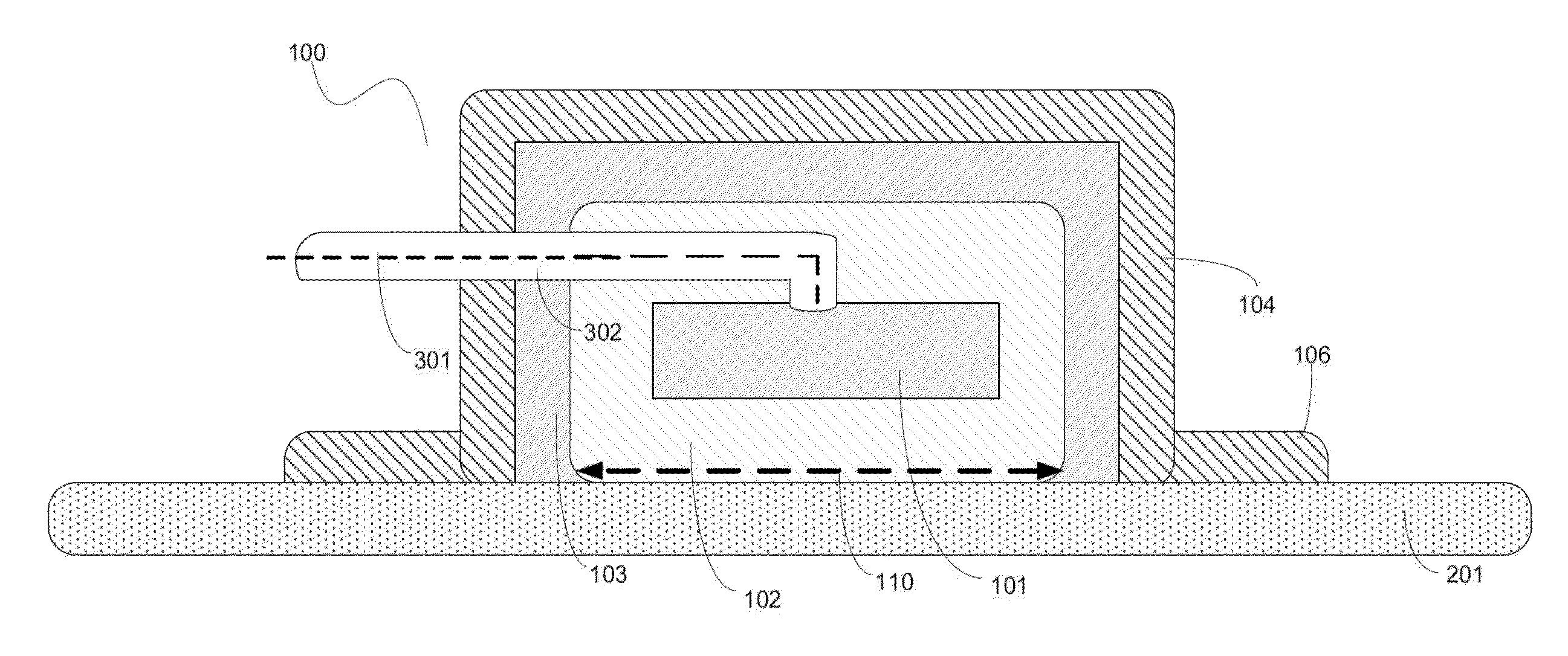
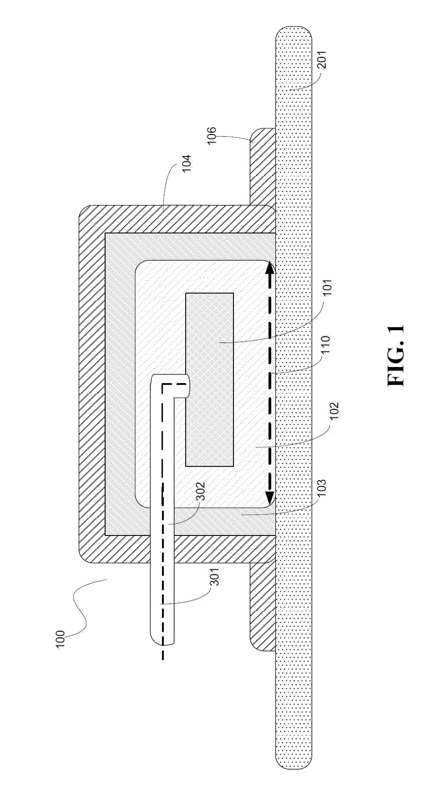
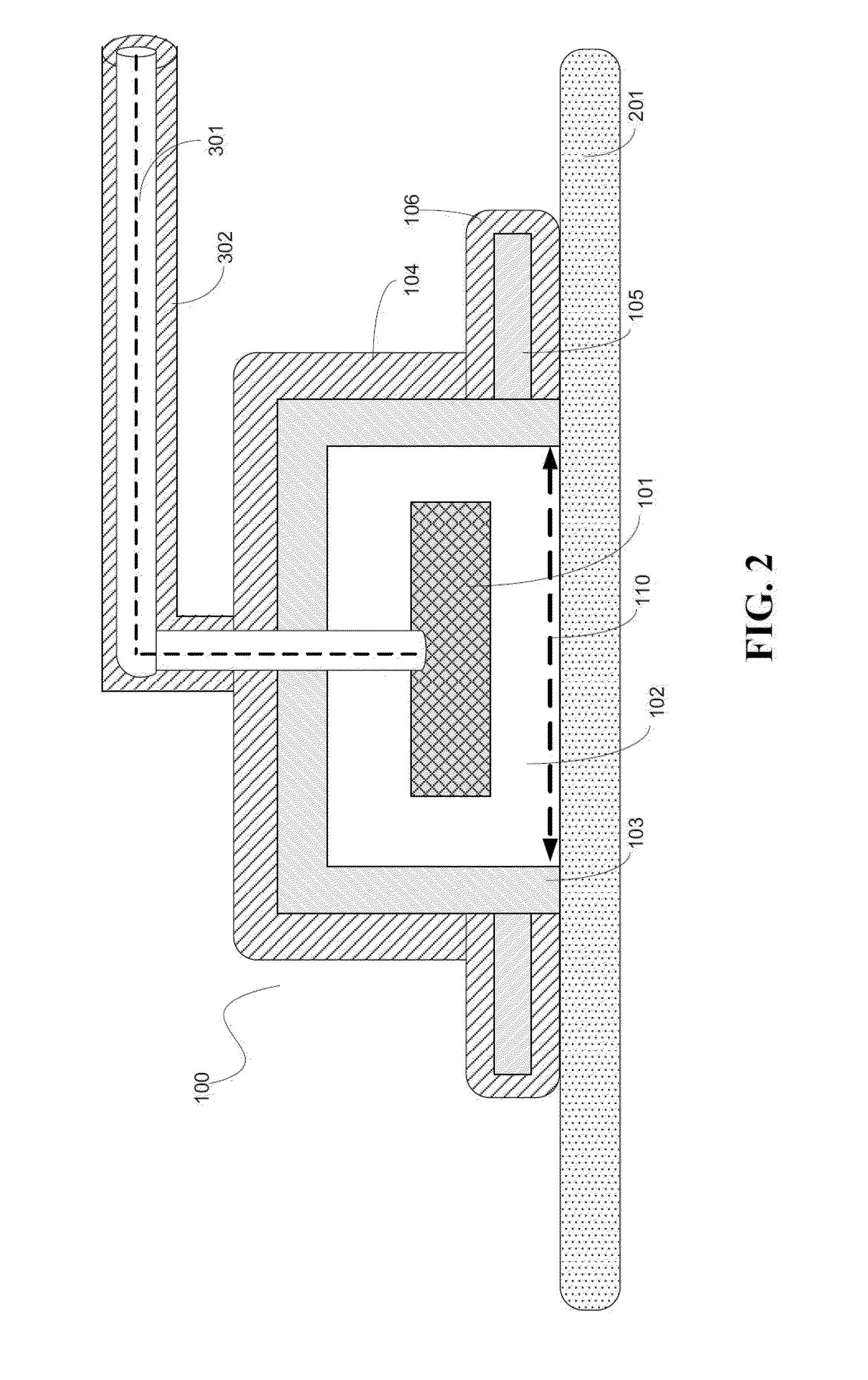
[0207]Reference is now made to FIGS. 11A, 11B and 11C, which are images of respectively, surface current density in an EM probe without a layer of absorbing material and a surface current density in an EM probe with a layer of absorbing material covering both sides of a circumferential flange as well as covering a cup shaped cavity, and a current density in an EM probe with a layer of absorbing material covering the bottom side only of a circumferential flange, according to some embodiments of the present invention. Reference is also made to FIGS. 12A, 12B and 12C, which are images of, respectively, H-field distribution in an EM probe without a layer of absorbing material and a H-field distribution in an EM probe with a layer of absorbing material covering both sides of a circumferential flange as well as covering a...


PUM


Abstract

An adhesive patch for attaching at least one EM probe to a subject's body, the adhesive patch comprising a planar member having at least one layer of radiation absorbing material and having at least one opening formed within the radiation absorbing material to allow the propagation of EM radiation via the opening from one side of the planar member to the other. The adhesive patch further comprises at least one layer of an adhesive attached over at least part of a bottom surface of the planar member, which adhesive layer may be applied so as to form a pattern on the bottom surface, the pattern comprising at least one adhesive-covered portion and at least one adhesive-free portion.

Description

FIELD AND BACKGROUND OF THE INVENTION[0001]The present invention, in some embodiments thereof, relates to an electromagnetic EM probe and, more particularly, but not exclusively, to an EM probe for transmission and / or reception of electromagnetic radiation and a method of generating the EM probe.[0002]EM radiation, such as RF and MW radiation, is potentially useful means of monitoring and diagnosing body tissues. The dielectric properties of the tissues may be a basis of detecting various pathologies and physiological trends.[0003]Examples for using RF and MW radiation for monitoring and diagnosing body tissues is found, inter alia, in International patent application pub. No WO 2010 / 100649, International patent application pub. No WO 2009 / 031150, and / or International patent application pub. No 2009 / 031149, which are incorporated herein by reference. The design and fabrication of such EM probes present various challenges.[0004]During the last years, various EM probes have been devel...

Claims


Application Information

Patent Timeline
IPC IPC(8): A61B5/00A61B5/05
CPCA61B5/05A61B5/6833A61B5/0507A61B5/24
Inventor SAROKA, AMIRBERGIDA, SHLOMI
Owner SENSIBLE MEDICAL INNOVATIONS LTD
Why Eureka
Try Eureka