Door hinge

Active Publication Date: 2015-05-21
SIMONSWERK
View PDF27 Cites 4 Cited by
  • Summary
  • Abstract
  • Description
  • Claims
  • Application Information

AI Technical Summary

Benefits of technology

The patent describes a hinge mechanism for doors that allows for easy adjustment and secure mounting on the door panel or frame. The hinge mechanism includes tabs that are formed by die-cutting the upper sheet-metal part, which can be bent over to eliminate play. The tabs can be connected to the hinge by a screw, and a blind-rivet nut can also be used to further strengthen the connection. The hinge mechanism also includes a positive-fitting guide that allows for easy adjustment in two directions, and a double offset ensures even force distribution. Overall, the hinge mechanism provides a simple and reliable solution for adjusting and mounting doors.

Problems solved by technology

Here, the riveting process represents a relatively laborious process step.

Method used


Image

  • Door hinge
  • Door hinge
  • Door hinge

Examples


Embodiment Construction

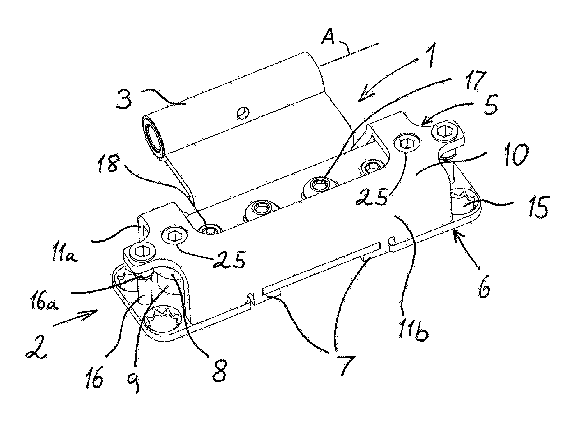
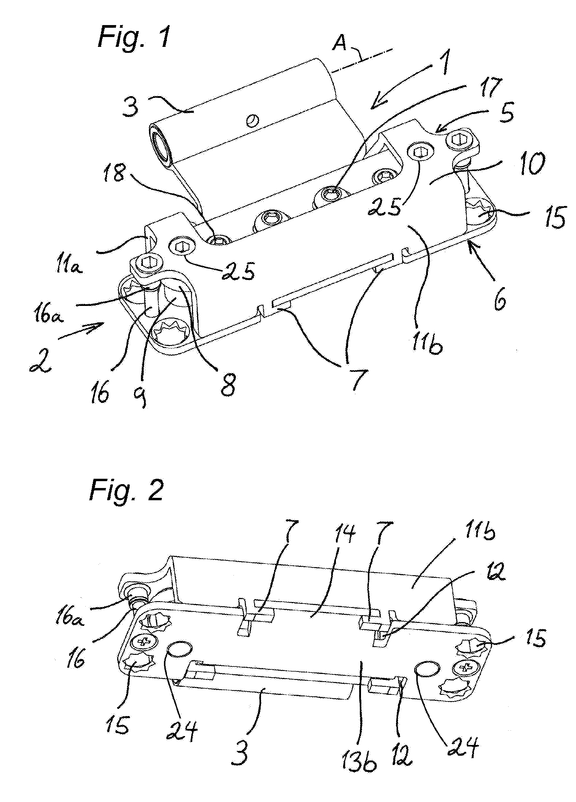
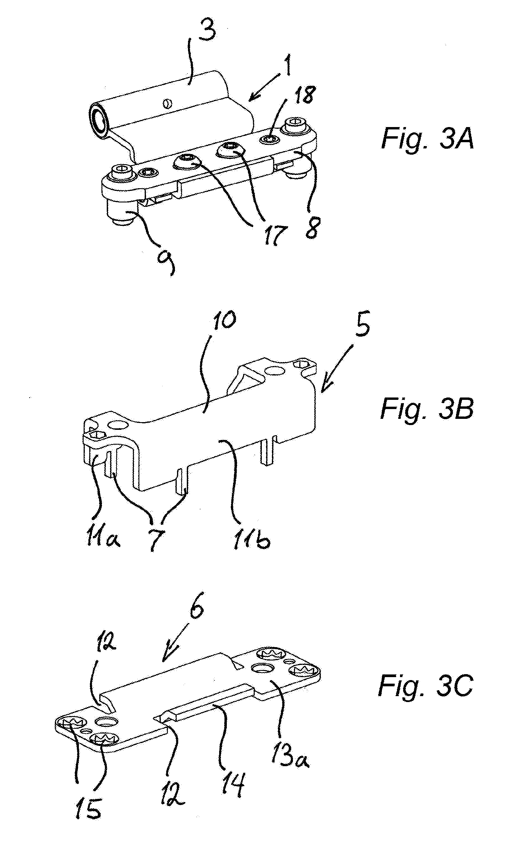
[0037]As seen in FIG. 1 a first hinge leaf 1 is adjustably secured in a housing 2 and is rotatable about an axis A at a hinge knuckle 3 formed with a second hinge leaf 4 shown in FIGS. 6 and 7. FIGS. 1 and 3 show how a housing 5 formed of two sheet-metal parts 5 and 6. The part 5 is of one piece and generally U-shaped and the part 6 is flat and has planar faces 13a and 13b. FIGS. 3B and 3C show the two sheet-metal parts 5 and 6 separately, before assembly. When the two sheet-metal parts 5 and 6 are fitted together, tabs 7 unitarily formed on the top part 5 are bent over so that the two sheet-metal parts 5 and 6 are attached to one another in a positive-fit such that they cannot be separated without damage to the parts.

[0038]Before the two sheet-metal parts 5 and 6 are attached to one another during assembly, resulting in a permanent connection, the first hinge leaf 1 is inserted between the two sheet-metal parts 5 and 6 along with a rigid cast-metal base plate 8. Here, the base plat...


PUM


Abstract

A door hinge has two hinge leaves joined together at a knuckle defining a hinge axis about which the leaves are relatively pivotal. Top and bottom sheet-metal parts forming a housing surround one of the hinge leaves. The top part is formed with a plurality of downwardly projecting side flaps each projecting toward and bearing on an upper face of the bottom part. Each side flap is formed with at least one downward projecting tab that extends past, is bent over, and bears upward against a bottom face of the bottom part. Two rotatable adjustment spindles are each journaled in the housing and threaded in the one leaf so that rotation of the spindles moves the one leaf in a first direction perpendicular to the hinge axis.

Description

FIELD OF THE INVENTION[0001]The present invention relates to a door hinge. More particularly this invention concerns a door hinge that can be adjusted after mounting between a door frame and an edge of a door panel.BACKGROUND OF THE INVENTION[0002]A known door hinge has a first and a second hinge leaf that are pivoted together at a knuckle defining a normally vertical pivot axis. The first leaf is adjustably secured in a sheet-metal holder or housing typically recessed in the door frame, although it could be set also in the edge of a door panel. The second hinge is normally secured immovably to the door edge facing the frame, although when the housing is in the door it could be on the face of the door frame. The first leaf is normally supported in the housing on two normally horizontal threaded spindles having axes extending perpendicular to the pivot axis. The spindles are rotatable about their axes in the holder to move the leaf normally horizontally in or out to adjust the gap be...

Claims


Application Information

Patent Timeline
IPC IPC(8): E05D7/04E05D3/02
CPCE05D7/04E05D2007/0469E05D3/022E05D2007/0476E05Y2900/132E05Y2201/638E05Y2600/634E05D7/0423E05D3/02E05D5/06E05D11/0054E05D2011/0063
Inventor BARTELS, THOMASBULTSCHNIEDER, ANDREGORENBACHER, SERGEI
Owner SIMONSWERK
Why Eureka
Try Eureka