
Buckle assembly

Active Publication Date: 2015-05-21
PLUS MEDITECH
View PDF3 Cites 5 Cited by
  • Summary
  • Abstract
  • Description
  • Claims
  • Application Information

AI Technical Summary

Benefits of technology

The purpose of this patent is to come up with a buckle assembly that can overcome the problems of the previous designs.

Problems solved by technology

However, pressing of the legs to disengage the male and female buckle parts is relatively inconvenient.

Method used


Image

  • Buckle assembly
  • Buckle assembly
  • Buckle assembly

Examples


Embodiment Construction

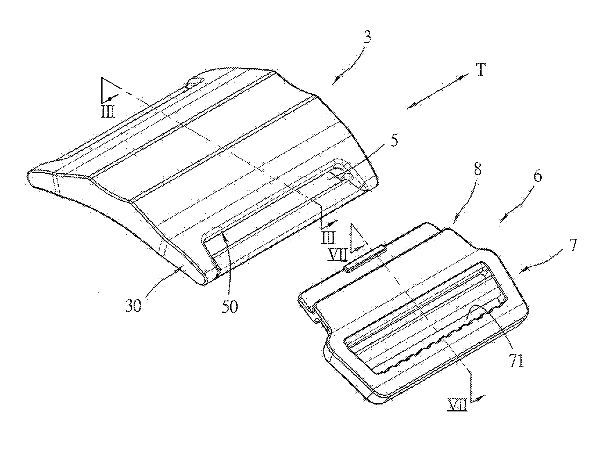
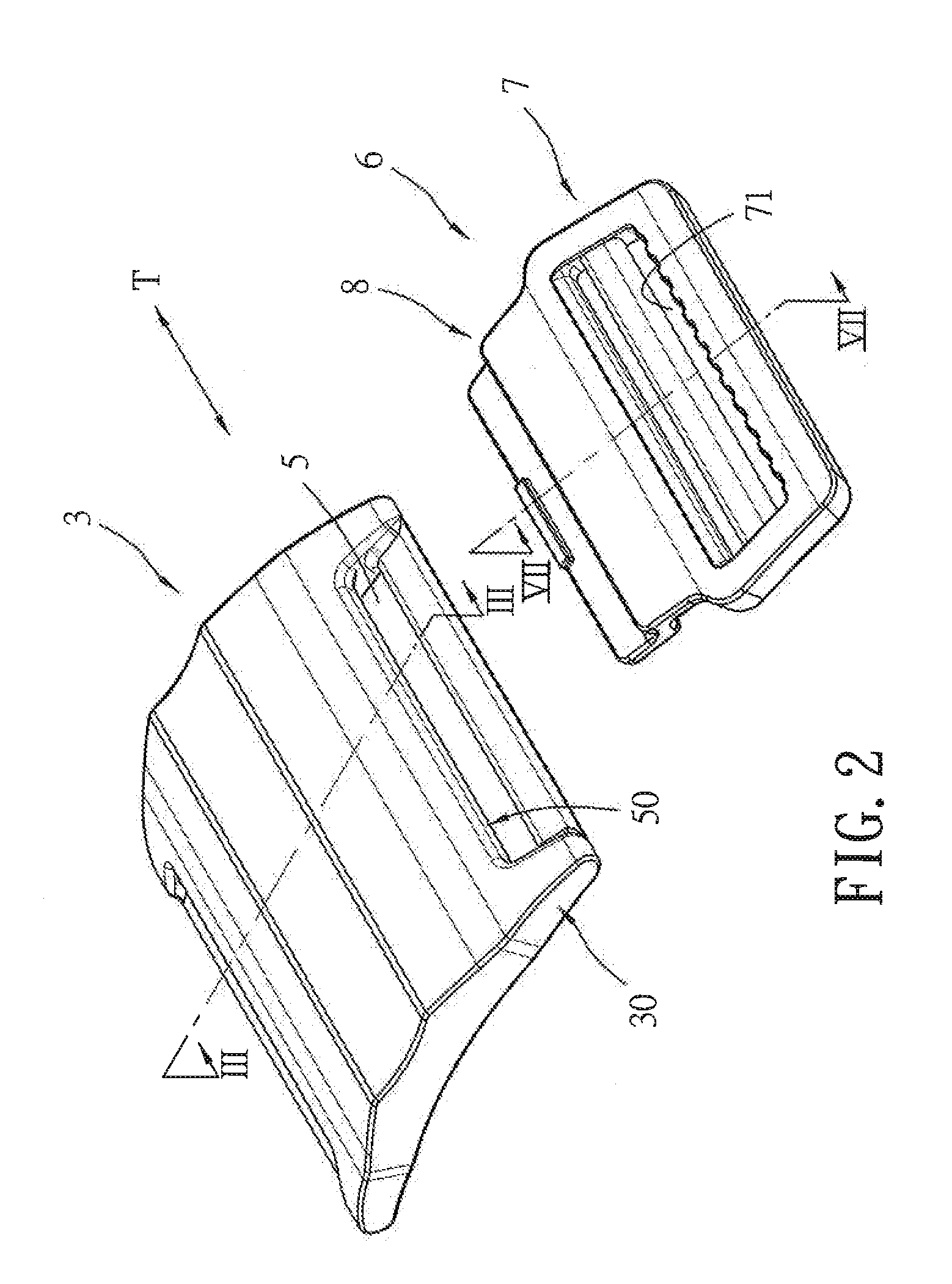
[0022]FIGS. 2 to 7 illustrate the preferred embodiment of a buckle assembly according to the present invention. The buckle assembly includes female and male buckle plates 3, 6.

[0023]The female buckle plate 3 has top and bottom surfaces 33, 34 and a slotted end portion 30. The slotted end portion 30 is formed with an insertion slot 5 that extends through the top and bottom surfaces 33, 34 and that is defined by a slot-defining wall 50. The slot-defining wall 50 has a first wall face 314 that extends from the top surface 33 to the bottom surface 34, and a second wall face 43 that extends from the top surface 33 to the bottom surface 34 and that is spaced apart from and that opposes the first wall face 314. The top surface 33 cooperates with the first and second wall faces 314, 43 to define first and second corners 311, 42, respectively. The second wall face 43 is perpendicular to a reference plane (Pf) and has an edge that lies on the reference plane (Pf). The first wall face 314 is p...


PUM


Abstract

A buckle assembly comprises female and male buckle plates. The female buckle plate is formed with an insertion slot defined by a slot-defining wall having first and second wall faces, and has first and second corners. The first and second corners oppose each other, and are different in height with respect to a reference plane. The male buckle plate has a bent end portion that has upper and lower segments and a middle segment cooperating with the upper and lower segments to define upper and lower corners. The bent end portion is pivotable to the first corner by abutting the upper corner against the first corner, such that the bent end portion is rotatable relative to the first corner.

Description

CROSS-REFERENCE TO RELATED APPLICATION[0001]This application claims priority of Taiwanese Application No. 102142048, filed on Nov. 19, 2013.BACKGROUND OF THE INVENTION[0002]1. Field of the Invention[0003]This invention relates to a buckle assembly, more particularly to a buckle assembly that includes a female buckle plate having a slot-defining wall that has first and second corners which are different in height with respect to a reference plane.[0004]2. Description of the Related Art[0005]U.S. Patent Application Publication No. 2013 / 0232743 discloses a buckle assembly that includes male and female buckle parts which are releasably engageable to each other through engaging portions. Two opposite legs are included in the buckle assembly, and are pressable to disengage the male and female buckle parts. However, pressing of the legs to disengage the male and female buckle parts is relatively inconvenient.[0006]FIG. 1 illustrates a conventional quick release buckle assembly that include...

Claims


Application Information

Patent Timeline
IPC IPC(8): A44B11/25A44B11/28
CPCA44B11/28A44B11/2588Y10T24/4522Y10T24/45241Y10T24/45272Y10T24/45984
Inventor CHIANG, YUEH-HUACHUANG, FU-LIN
Owner PLUS MEDITECH
Learn More