Switch structure with display and playback functions

Active Publication Date: 2015-05-21
CHU CHING HSIUNG
View PDF16 Cites 4 Cited by
  • Summary
  • Abstract
  • Description
  • Claims
  • Application Information

AI Technical Summary

Benefits of technology

The present invention is a switch structure with display and playback functions. The switch has a reduced internal space and requires less pressing force, which makes it easier to replace and maintain. The switch includes a cover with transparent or translucent portions, a holder with projections engaged with the cover, a base with engaging portions engaged with the cover, and an elastic supporting element made of flexible non-metal material that can absorb shock and cushion impact. The electrical connector is made of graphite and can be connected through two semicircular parts. The switch has a smaller thickness and allows for smoother motion of the mechanism.

Problems solved by technology

While the foregoing product effectively reduces the pressing force required, enhances the smoothness of movement of the entire mechanism, and enables easy maintenance and replacement, the internal structure for electrically connecting the circuit board to the LED screen—implemented by contact between the electrical contacts at the bottom of the movable support and the conductive terminals in the base—has the following drawbacks, despite the fact that the aforesaid design allows unhindered upward and downward movement of the movable support and that the electrical contacts have the incidental shock-absorbing and impact-cushioning effects.
First, the conductive terminals provided in the base hugely complicate the internal structure of the press-button switch.
Second, the distance between the base and the movable support increases the thickness of the switch, which goes against the current trend of making smaller and more compact switches.

Method used


Image

  • Switch structure with display and playback functions
  • Switch structure with display and playback functions
  • Switch structure with display and playback functions

Examples


Embodiment Construction

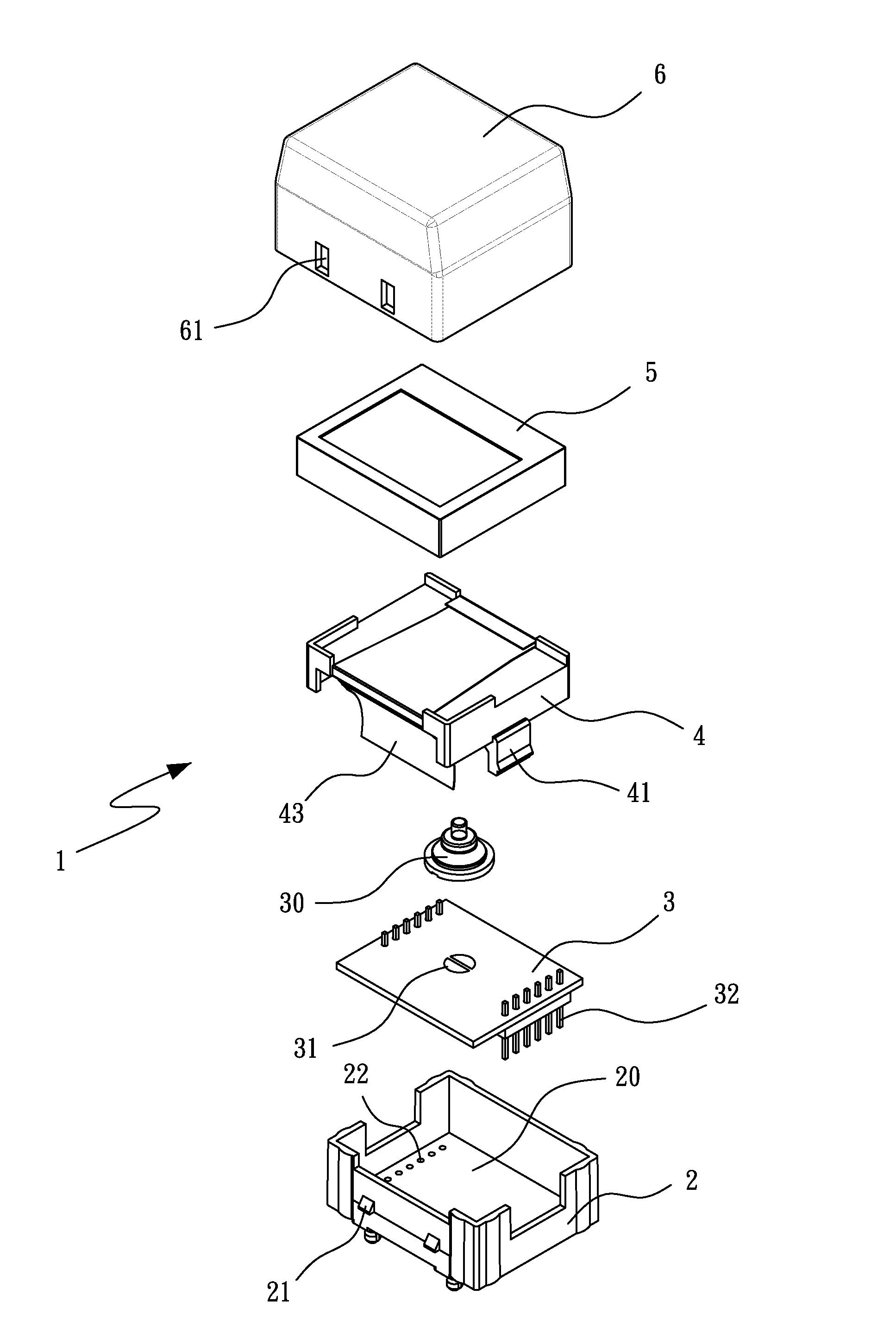
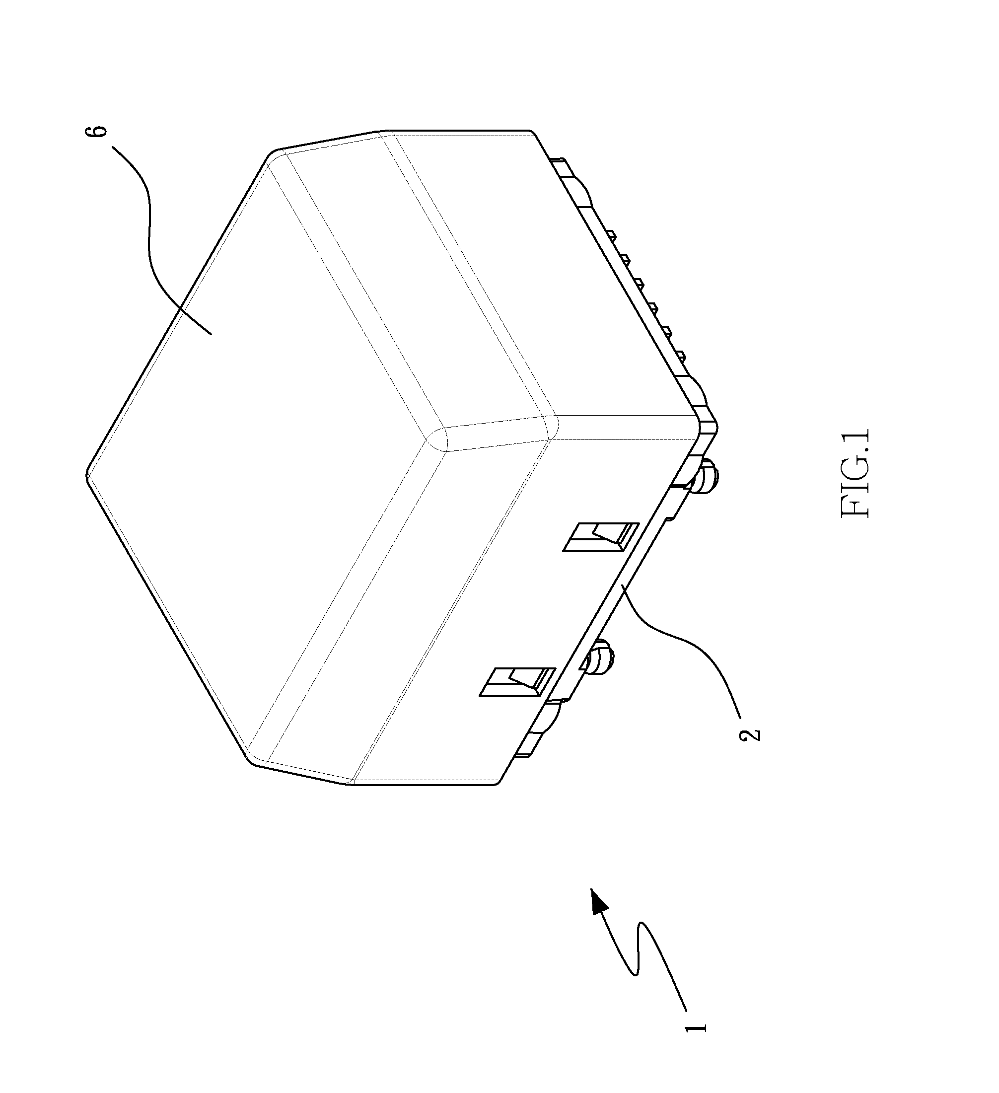
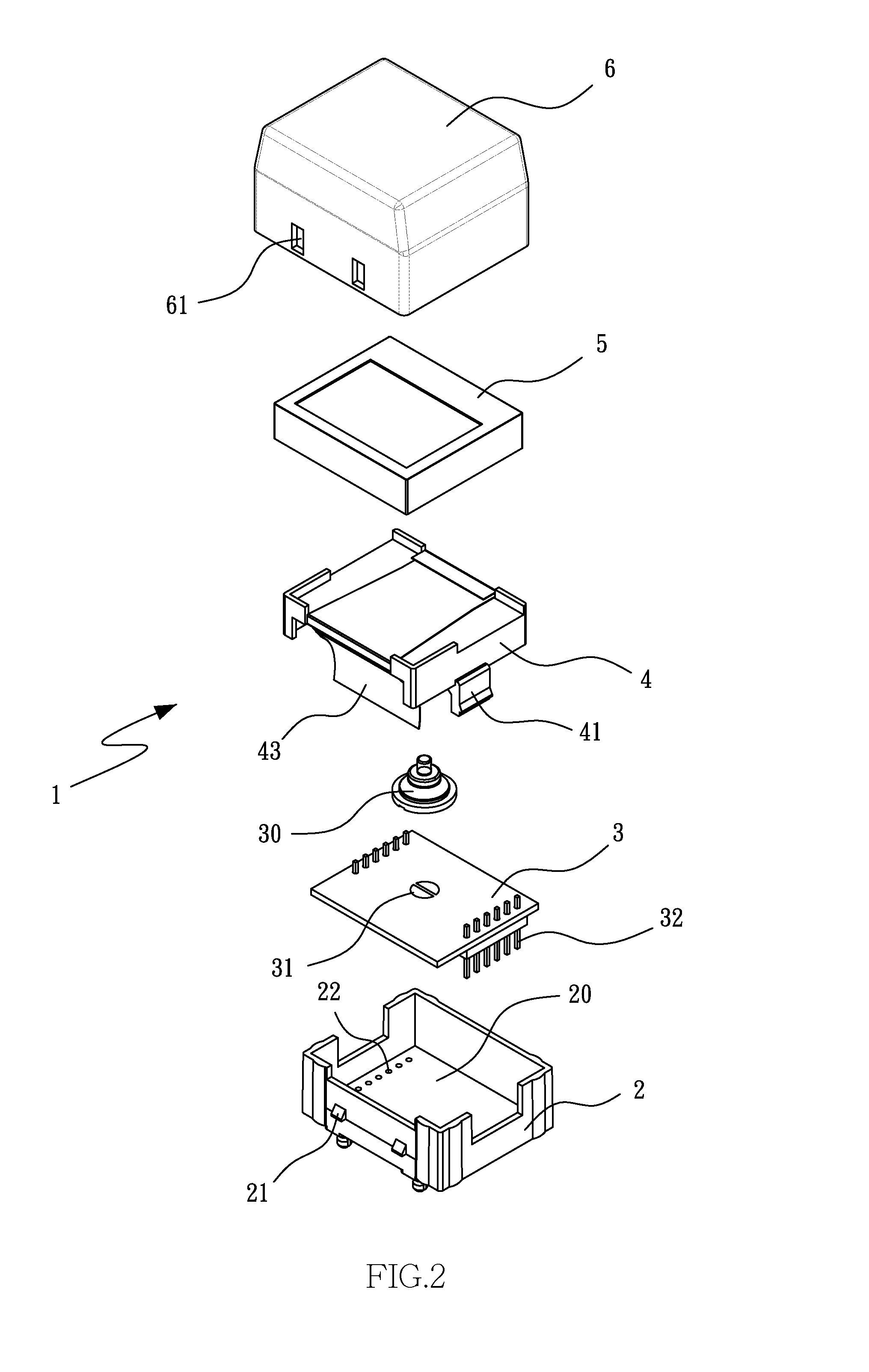
[0019]Referring to FIG. 1 to FIG. 5, a switch structure 1 with display and playback functions is designed to be mounted on a circuit board (not shown) on a fixing frame (not shown) and has the following essential components arranged from bottom to top: a base 2, a circuit board 3, a holder 4, a display screen 5, and a cover 6. The base 2 has a receiving space 20 and is provided with at least one engaging portion 21 on each of two opposite outer lateral sides. The bottom of the base 2 is provided with a plurality of through holes 22 on each of two opposite lateral sides. The circuit board 3 is received in the receiving space 20 and is peripherally provided with pins 32 which correspond in position to the through holes 22 respectively. The pins 32 are to be connected to the circuit board on the fixing frame. An electrical connection region 31 is provided on a surface of the circuit board 3 and is composed of two spaced-apart semicircular parts such that the electrical connection regio...


PUM


Abstract

A switch structure with display and playback functions includes a base, a circuit board, a holder, a display screen, and a cover. The circuit board is received in the base and has an electrical connection region. A supporting member and a flexible flat cable are provided below the holder. An elastic supporting element in the supporting member corresponds in position to the electrical connection region and is provided with an electrical connector. The display screen is provided on the holder and is electrically connected to the circuit board by the flexible flat cable. The cover covers the holder and the display screen. When the cover is pressed downward, thereby compressing the elastic supporting element, the electrical connector is contacted with, and closes the circuit of, the electrical connection region to connect the display screen to the circuit board. The switch structure features a small internal space and small thickness.

Description

BACKGROUND OF THE INVENTION[0001]1. Technical Field[0002]The present invention relates to the structural design of press-button switches and, more particularly, to a switch structure having display and playback functions.[0003]2. Description of Related Art[0004]An improved electrical connection structure for use in a press-button switch is now commercially available. Basically, a flexible flat cable is provided in a base and is connected to the circuit board supported on a movable support. When the switch housing is pressed, a frame therein and the movable support are moved downward such that the electrical contacts at the bottom of the movable support are in contact with the conductive terminals in the base to provide electrical connection. The flexible flat cable, which changes its physical configuration with the upward and downward movement of the frame and the movable support, does not require additional force to be applied when pressing the switch housing. Once the movable supp...

Claims


Application Information

Patent Timeline
IPC IPC(8): H01H13/10H01H13/02H01H13/14
CPCH01H13/10H01H13/14H01H13/023H01H2207/04H01H2227/002H01H2207/004H01H2219/002H01H9/181
Inventor CHU, CHING-HSIUNG
Owner CHU CHING HSIUNG
Why Eureka
Try Eureka