
Convective microwave oven

A microwave oven and convection chamber technology, which is used in household stoves/stoves, household heating, lighting and heating equipment, etc., can solve the problems of low wind speed of centrifugal fans, slow cooking speed, and high temperature at the rotating shaft, so as to improve the heat dissipation effect, The effect of preventing excessive accumulation and improving assembly efficiency

Inactive Publication Date: 2013-03-27
LG ELECTRONICS (TIANJIN) APPLIANCES CO LTD
View PDF8 Cites 0 Cited by
  • Summary
  • Abstract
  • Description
  • Claims
  • Application Information

AI Technical Summary

Problems solved by technology

[0005] As disclosed in the above two patents, the hot air convection systems of the existing convection microwave ovens all use centrifugal fans as the hot air driving source, and the centrifugal fans have low wind speed and small air volume, resulting in slow cooking speed and low energy efficiency. User acceptance of the product
[0006] Now there is a turbo fan introduced into the convection chamber of the convection microwave oven of the microwave oven. However, when the turbo fan bracket is matched with the shaft of the turbo fan, it is generally used to install ring balls and lubricating oil inside the bracket. When the shaft rotates, the ball will follow. When rotating, at normal temperature, the balls run smoothly due to the action of lubricating oil; however, the temperature inside the convection chamber is very high, and the temperature at the rotating shaft is also high. Melting and other problems seriously affect product quality

Method used


Image

  • Convective microwave oven
  • Convective microwave oven
  • Convective microwave oven

Examples


Embodiment Construction

[0019] In order to enable those skilled in the art to better understand the solution of the present invention, the present invention will be further described in detail below in conjunction with the accompanying drawings and embodiments.

[0020] The convection microwave oven of the present invention comprises a microwave oven body; a cooking cavity formed inside the microwave oven body; and an electronic accessory room provided with various electronic components. A cavity door constituting the front side of the microwave oven body and used for opening and closing the cooking cavity is installed on the front panel.

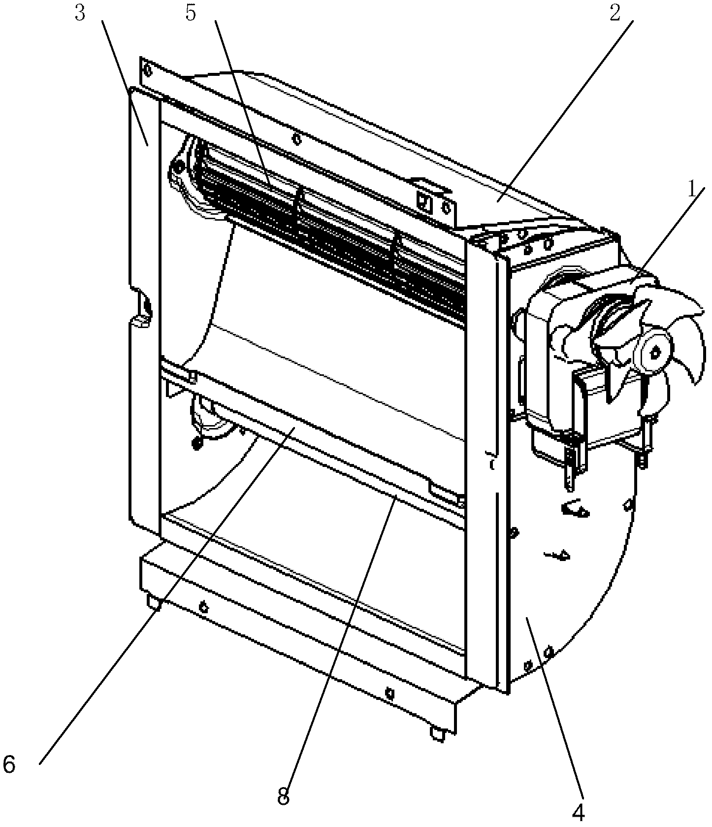
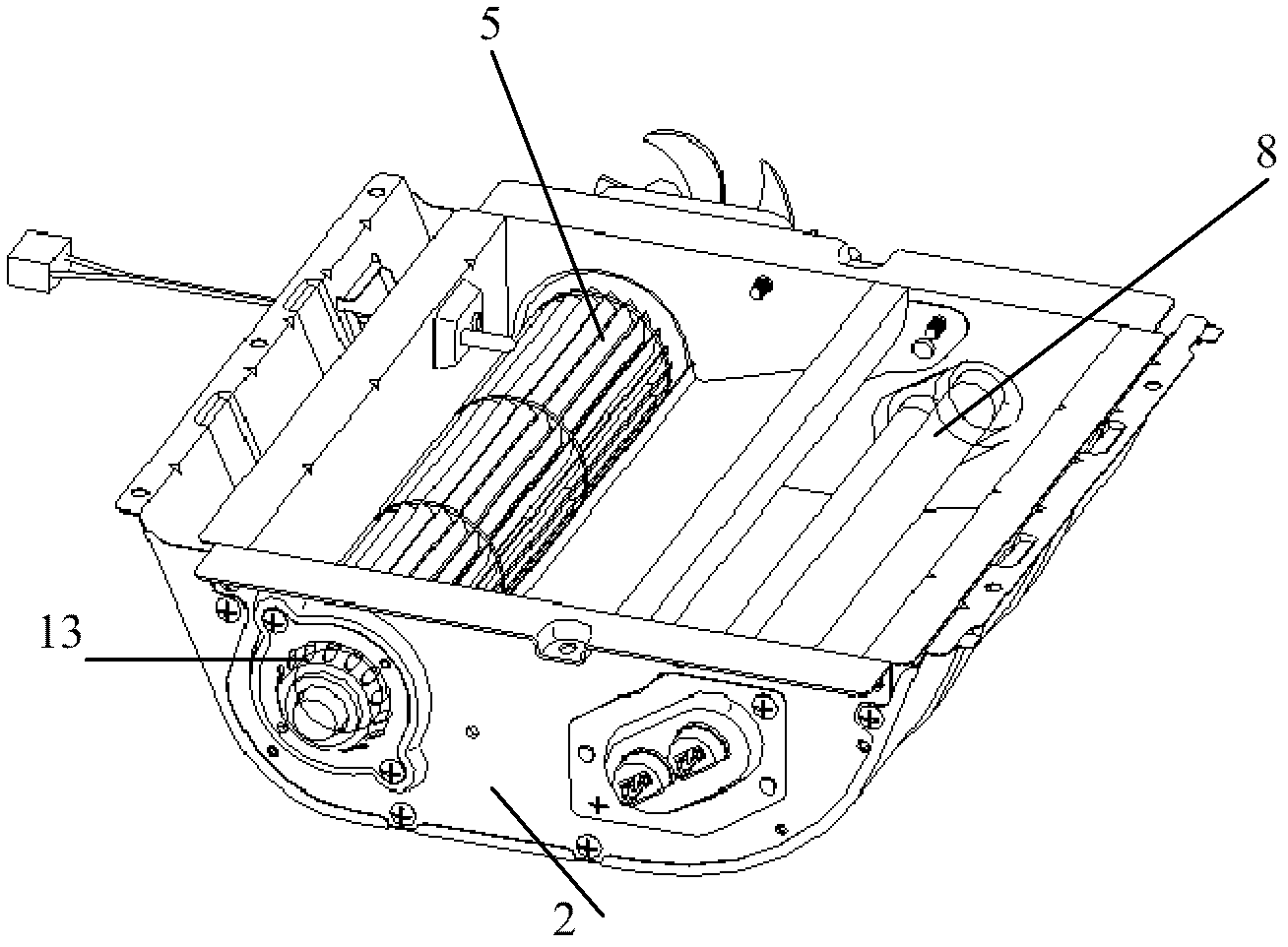
[0021] A plurality of communication holes communicating with the cooking cavity are formed on the rear panel of the microwave oven cooking cavity, and a convection chamber is arranged behind the rear panel. Such as figure 1 As shown, the convection chamber of the present invention is formed by a rear panel (not shown in the figure), a volute 2 that is fixedly con...


PUM


Abstract

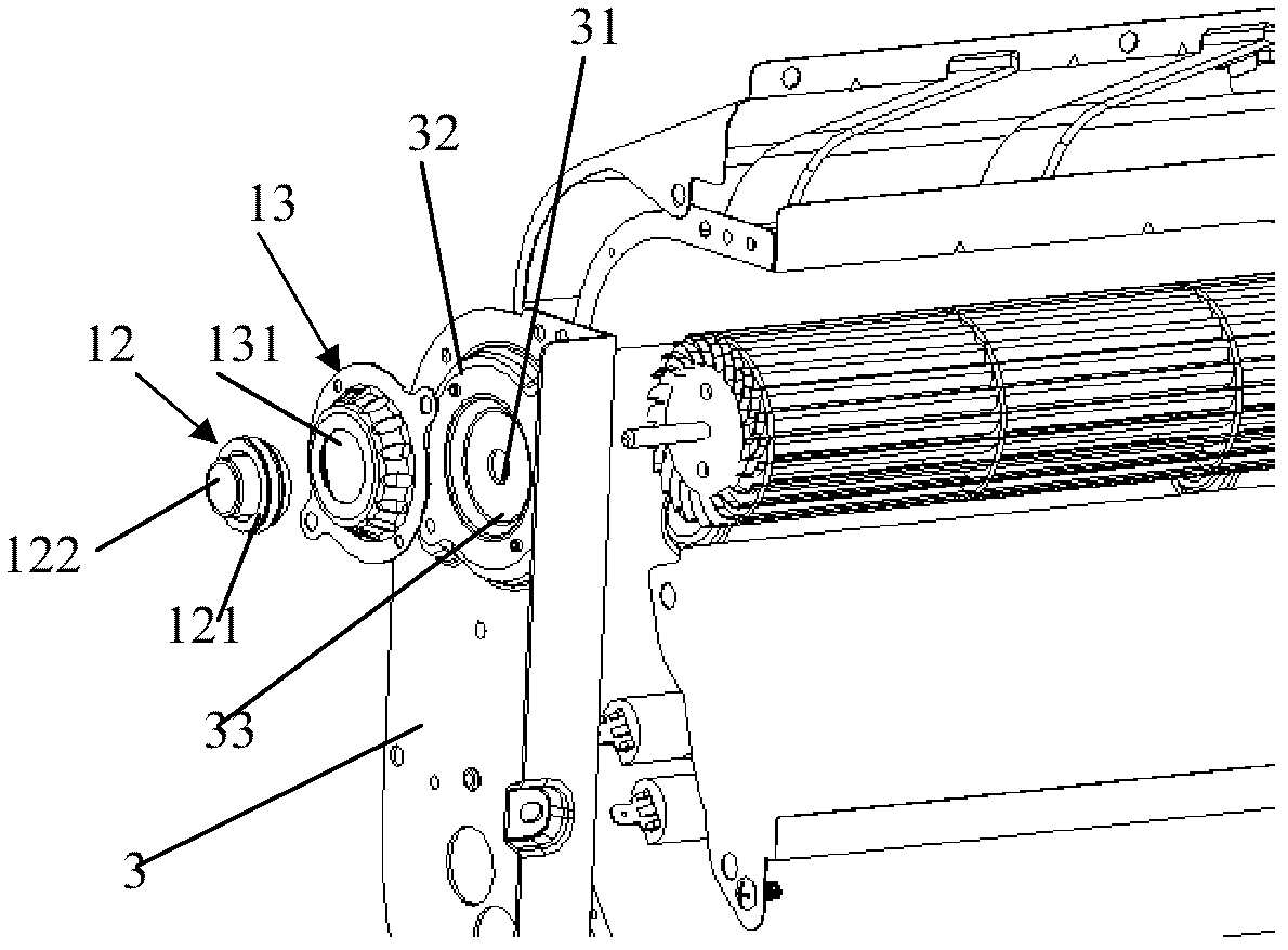
The invention discloses a convective microwave oven. The convective microwave oven adopts a turbine fan as a convective fan, a rotation shaft supporting structure is arranged between the rotation shaft of the turbine fan and a left side plate, the rotation shaft supporting structure comprises a copper shaft sleeved on the end portion of the rotation shaft, a rubber seat capable of containing the copper shaft, and a cover tureen which is separably fixedly connected to the outside of the left side plate and clamps the rubber seat. The fan rotation shaft supporting mechanism utilizes the smooth contact of the metal rotation shaft and the copper shaft to realize the relative smooth rotation of the two shafts without lubrication oil, so the influences on the shafts are small and the normal rotation of the shafts is guaranteed at a high temperature; the rubber seat is utilized to support and limit the copper shaft, so the shake of the rotation shaft is effectively absorbed, and the noise is reduced; and the deformable characteristic of the rubber is utilized to properly reduce the assembling precision in order to improve the assembling efficiency.

Description

technical field [0001] The invention relates to a convection microwave oven, in particular to a rotating shaft support structure of a turbo fan of the convection microwave oven. Background technique [0002] Generally speaking, a microwave oven is a machine that cooks food conveniently by turning on the power supply and using the microwave effect generated. Especially recently, in addition to the magnetron, heating sources such as heaters have been installed, and various cooking methods have appeared, such as convection microwave ovens, which have radiant heat and convective heat generated by electric heaters and fans. The function of food, and the main function of cooking food by microwave energy. Utilizing this convection microwave oven not only can food like fish be cooked evenly and thoroughly to their inner core by microwave energy, but also their surface is lightly toasted by hot air to produce delicious taste and show a better appearance . [0003] Chinese patent 9...

Claims


Application Information

Patent Timeline
IPC IPC(8): F24C7/02
Inventor 郭红涛宋瑞祥杜海春
Owner LG ELECTRONICS (TIANJIN) APPLIANCES CO LTD
Learn More