Container End Closure with a Score Feature

Active Publication Date: 2015-05-21
BALL CORP
View PDF1 Cites 15 Cited by
  • Summary
  • Abstract
  • Description
  • Claims
  • Application Information

AI Technical Summary

Benefits of technology

[0008]These and other needs are addressed by the various embodiments and configurations of the present invention. This invention relates to a novel system, device, and method for providing a food a

Problems solved by technology

Additionally, known end closures may buckle when under varying temperatures and internal pressure.
If an end closure buckles near the score line and opening, then the score line can crack and release the contents of the container.
This is called “peak and leak.” Thus, end closures are often designed to withstand bu

Method used


Image

  • Container End Closure with a Score Feature
  • Container End Closure with a Score Feature
  • Container End Closure with a Score Feature

Examples


second embodiment

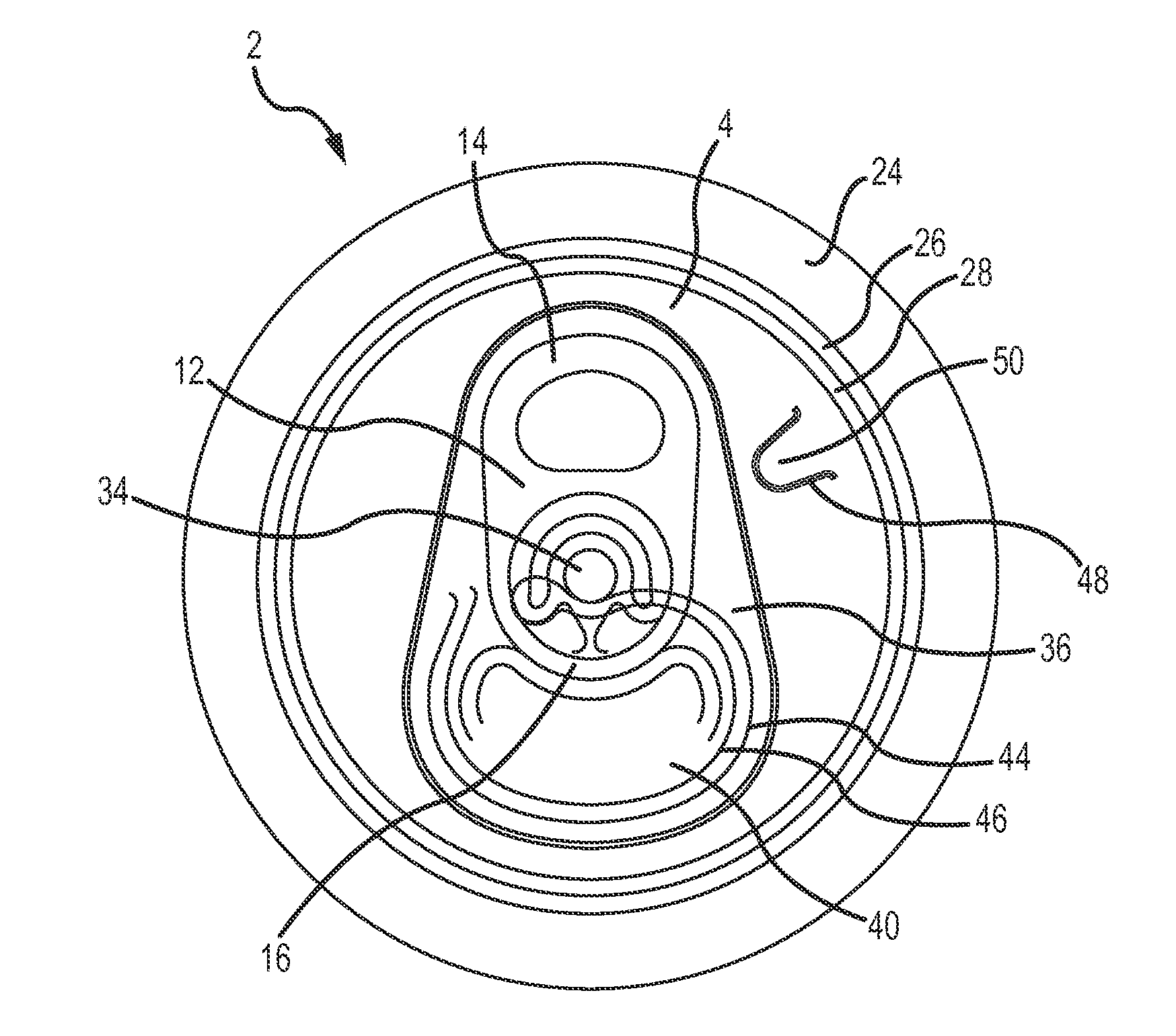
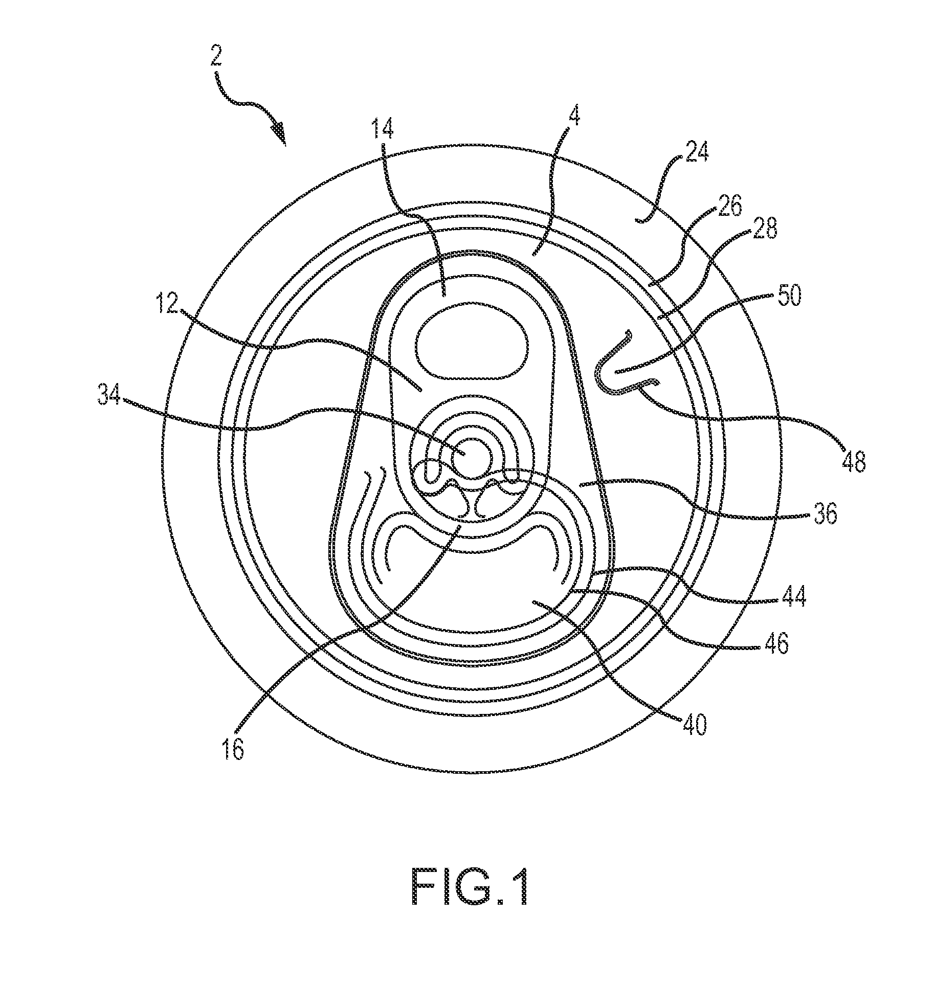
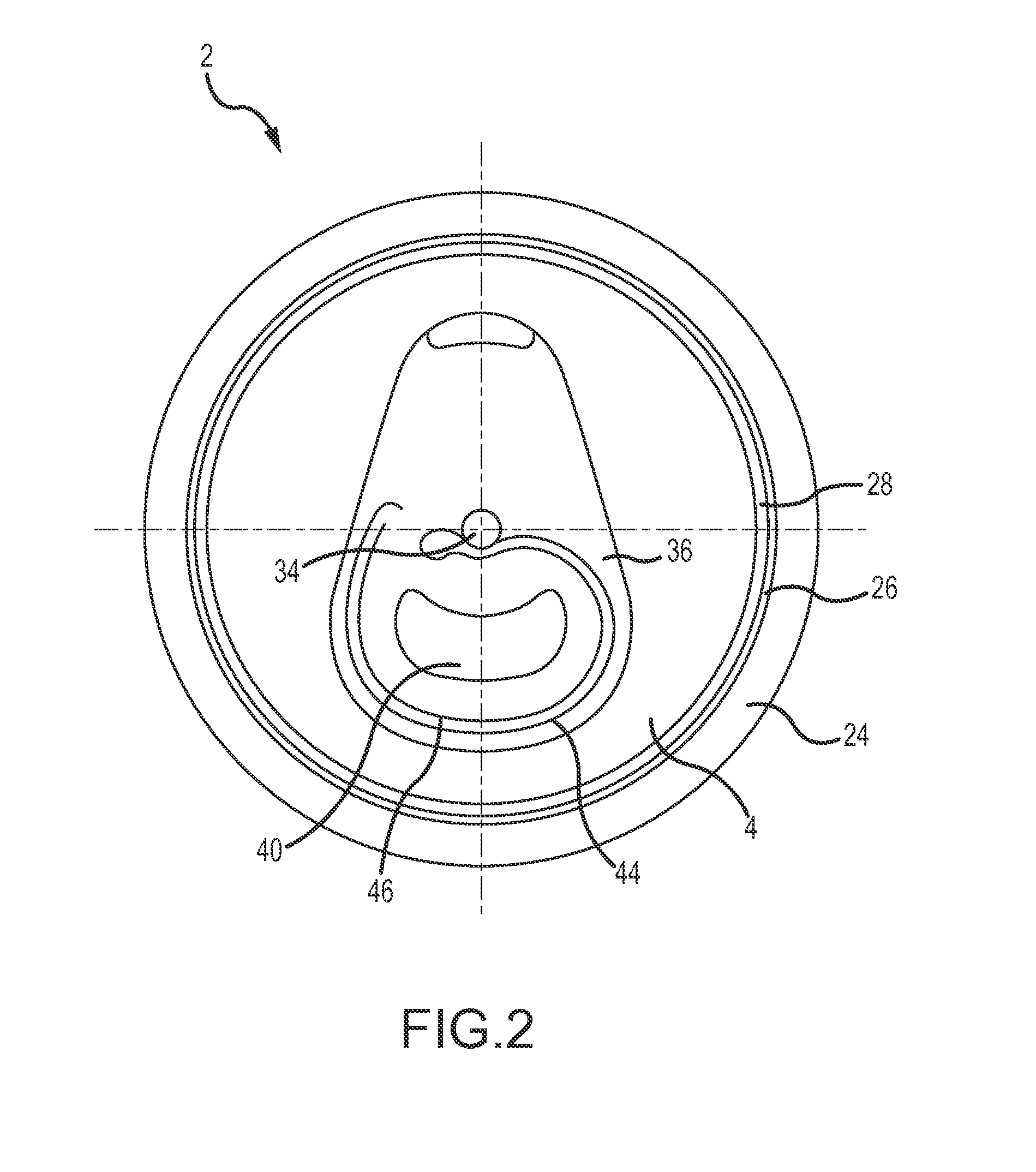
[0063]FIG. 2 shows the public side of an end closure 2. The end closure 2 is shown without a tab. The end closure 2 comprises a peripheral curl 24 interconnected to a chuck wall 26, which is interconnected on a lower end to a countersink 28. The countersink 28 is interconnected to a center panel 4, which includes a rivet 34, a deboss area 36, and a tear panel 40 defined by a primary score line 44. The tear panel 40 also has a secondary score line 46 that is parallel to the primary score line 44.

[0064]FIGS. 3A-3D show a score line of existing designs. FIG. 3A shows a top plan view of the score line 38 and a load 6 positioned proximate to the score line 38. FIG. 3B a side elevation view of the material with the score before the load 6 is applied near the score. FIG. 3C shows a side elevation view of the material with the score after the load 6 is applied near the score. FIG. 3D shows a sectional view of the material with the score line 38 at cut 3D-3D of FIG. 3A.

[0065]FIG. 4A shows a ...

third embodiment

[0072]FIG. 8A shows a top plan view of the form 30 with a width W1 and defined by a form perimeter 32. In one embodiment, W1 ranges between approximately 0.100 inches and 0.600 inches. In a more preferred embodiment, W1 ranges between approximately 0.150 inches and 0.500 inches. In a most preferred embodiment, W1 ranges between approximately 0.200 inches and 0.400 inches. This form 30 has a focalized area 54 near the center of the form 30, where the features have been sharpened (i.e., smaller radii) to focus the forces and loads into the center of the form 30. The focalized area 54 acts like a stress concentrator to promote permanent deformation of the form 30. When a load is applied to a structure, the load causes the structure to stress. A stress concentrator forces the stress to be higher in a specific, focalized area. By focusing all of the stress to a small area, the small area will fail sooner than it would fail without the concentrated stress. Thus, when a load is applied to ...

fourth embodiment

[0074]FIG. 9 shows the cross-section of a form 30 with a score line 38. This embodiment has a one-sided collapsible form 30 with a non-symmetrical cross-section having a height H1, width W1, and a form area 30. In one embodiment, W1 ranges between approximately 0.100 inches and 0.600 inches. In a more preferred embodiment, W1 ranges between approximately 0.150 inches and 0.500 inches. In a most preferred embodiment, W1 ranges between approximately 0.200 inches and 0.400 inches. In one embodiment, H1 ranges between approximately 0.005 inches and 0.050 inches. In a more preferred embodiment, H1 ranges between approximately 0.010 inches and 0.030 inches. In a most preferred embodiment, H1 ranges between approximately 0.015 inches and 0.025 inches. The form cross-section has one substantially vertical side 60 and a curved side 62. The form 30 also has a score line 38 and two coined areas: a first coined area 58 having a width W2 and a second coined 60 having a width W3. In one embodimen...


PUM


Abstract

An end closure for food and beverage containers is provided. The end closure comprises a score fracture force reduction feature. Thus, less force is required by a user to fracture the score and open the opening in the end closure. In one embodiment, the score fracture force reduction feature is a collapsible form raised above the center panel and having a score line and a coined area.

Description

RELATED APPLICATION[0001]This application claims the benefit of U.S. Provisional Patent Application Ser. No. 61 / 906,796, filed Nov. 20, 2013, entitled “Container End Closure with a Score Feature,” which is hereby incorporated by reference in its entirety.FIELD OF THE INVENTION[0002]Embodiments of the present invention generally relate to containers and container end closures, and more specifically metallic beverage container end closures with a score fracture force reduction feature.BACKGROUND OF THE INVENTION[0003]Containers, and more specifically metallic beverage containers, generally contain a neck on an upper portion that is adapted for interconnection to a metallic end closure. The container end closure is formed from a flat sheet of metallic material and generally includes a pull tab or other form of stay on tab (“SOT”). Beverage containers commonly store carbonated beverages, thus, both the container body and the container end closure are required to withhold internal pressu...

Claims


Application Information

Patent Timeline
IPC IPC(8): B65D17/00B21D51/38
CPCB65D17/165B21D51/383B65D17/02B65D17/4012B65D17/404B65D2517/0089B65D2517/0094
Inventor CHASTEEN, HOWARD C.SCOTT, ANTHONY J.JACOBER, MARK A.
Owner BALL CORP
Why Eureka
Try Eureka