
Telescopic Wing and Rack System for Automotive Airplane

a technology for automobile airplanes and racks, which is applied in the direction of aircraft, wing adjustment, transportation and packaging, etc., can solve the problems of limited success, difficult to allow for easy conversion to a vehicle that uses wings to achieve flight in the air, and awkward transition between the two modes for the operator, etc., to achieve the effect of small storage volume and simple conversion

Inactive Publication Date: 2015-05-21
MCCOY JEREMIAH BENJAMIN BOWE
View PDF0 Cites 27 Cited by
  • Summary
  • Abstract
  • Description
  • Claims
  • Application Information

AI Technical Summary

Benefits of technology

The present invention is an automotive aircraft that can be easily attached to a car or other vehicle and flown like a small personal aircraft. It uses telescoping wings that can be folded up for driving on roads and extended for flying. The wing system is attached to a wing rack system that can be folded back for road driving. This invention offers a simple and flexible solution for combining the benefits of aircraft and automobiles.

Problems solved by technology

There have been many inventors and patents over the years that have attempted to accomplish a successful union of the ability to drive and the ability to fly into a single vehicle, with very limited success.
The primary problems leading to this difficulty come mostly from the fact that the two modes of operation have very different design requirements and the conversion between the two modes can be an awkward transition for the operator.
Creating a design that can easily accommodate the spatial requirements and safety features of an automobile on the roads while allowing for an easy conversion to a vehicle that uses wings to achieve flight in the air is a difficult challenge.

Method used


Image

  • Telescopic Wing and Rack System for Automotive Airplane
  • Telescopic Wing and Rack System for Automotive Airplane
  • Telescopic Wing and Rack System for Automotive Airplane

Examples


Embodiment Construction

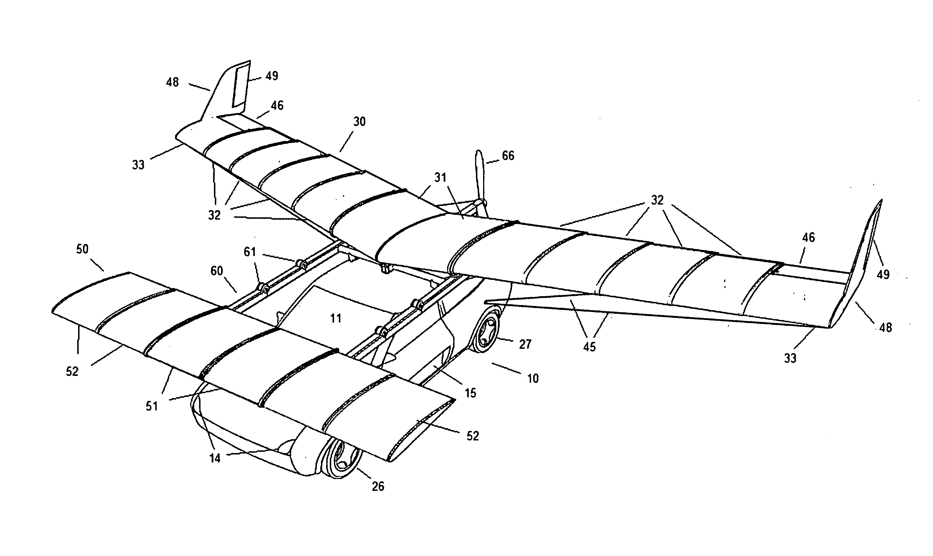
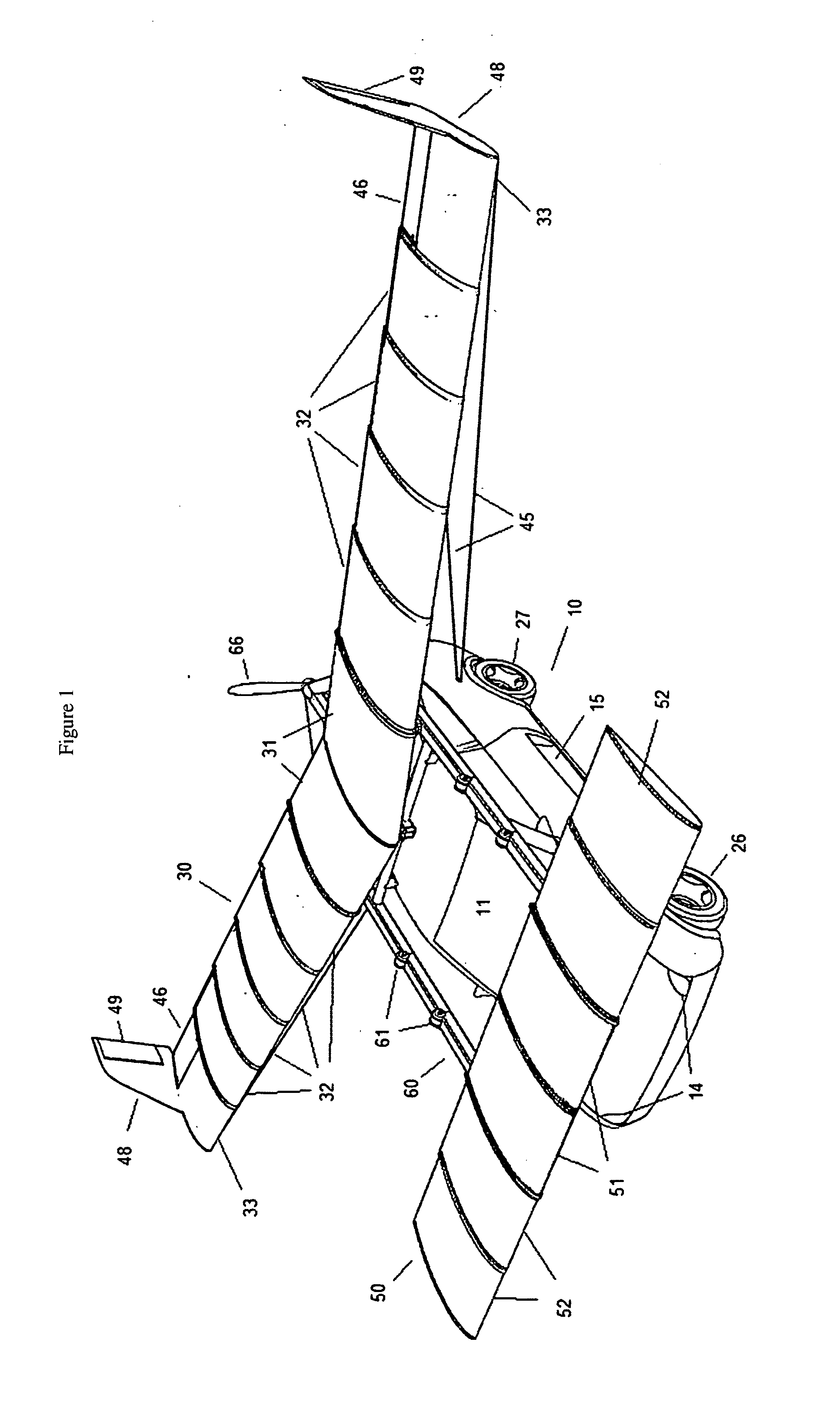
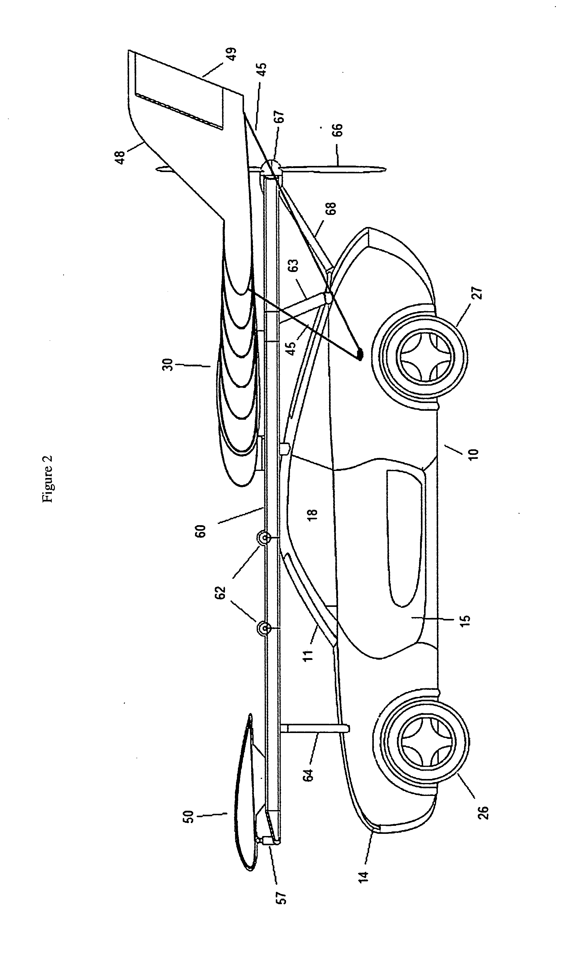
[0048]Referring now to the invention as shown in FIGS. 1 and 2 is an automotive aircraft with rear main wings 30 and forward canard wings 50 attached to a wing rack frame 60 in configuration for flight. The wing rack frame 60 is designed to support two sets of wings, the main wings 30, and forward canards 50 connecting them to the vehicle body 10. The wing rack frame 60 is attached to the vehicle body and held by support struts 63, 64. The vehicle body 10 is typical of an automobile with front and rear wheels 26, 27 arranged in a traditional wheel pattern, containing a passenger compartment with doors 15, windshield 11 and all the typical safety and operational mechanisms of an automobile.

[0049]Referring in more detail to the invention as shown in FIGS. 1 and 2, the main wings 30 extend from the wing rack frame 60 over the rear wheels 27 and the forward canards 50 extend from the wing rack frame 60 over the front wheels 26. The main wings 30 are comprised of individual sections 31, ...


PUM


Abstract

The invention is a vehicle for personal transportation with the ability to convert between two alternate modes of transport, as an automobile for transportation on roads and as a personal aircraft for travel between municipal airports, utilizing retractable telescoping wings and a foldable frame.

Description

BACKGROUND OF THE INVENTION[0001]The present invention is in the technical field of automobiles and personal aircraft. More particularly, the present invention is in the technical field of systems capable of converting between an automobile and an aircraft.[0002]The idea of combining the capabilities of an automobile and an aircraft in a single vehicle is nearly as old as the original inventions themselves. There have been many inventors and patents over the years that have attempted to accomplish a successful union of the ability to drive and the ability to fly into a single vehicle, with very limited success. The primary problems leading to this difficulty come mostly from the fact that the two modes of operation have very different design requirements and the conversion between the two modes can be an awkward transition for the operator. Creating a design that can easily accommodate the spatial requirements and safety features of an automobile on the roads while allowing for an e...

Claims


Application Information

Patent Timeline
IPC IPC(8): B64C3/56B64D27/26
CPCB64D27/26B64C3/56B64C37/00
Inventor MCCOY, JEREMIAH BENJAMIN BOWE
Owner MCCOY JEREMIAH BENJAMIN BOWE
Learn More