
Short physical-layer control frames

Active Publication Date: 2015-05-21
ORANGE SA (FR)
View PDF9 Cites 3 Cited by
  • Summary
  • Abstract
  • Description
  • Claims
  • Application Information

AI Technical Summary

Benefits of technology

The invention is a method for transmitting a control frame between two entities. The method includes a modulation step using a single modulation technique, which allows for a shorter control frame and reduces the bandwidth taken. The inserted information from a second layer can be obtained by using the first layer header field. This method also reduces the number and complexity of demodulation operations and increases transmission robustness. Overall, the invention improves efficiency and reliability in data transmission.

Problems solved by technology

The reason is that the modulated signals have a different range depending on the speed used; the higher the speed, the shorter the range of the signal and the higher the risk of error on reception.
This is the case particularly with voice over IP traffic and data traffic between machines, where the bandwidth occupied by the control frames is a problem.
Moreover, the presence of an MAC header modulated at a higher speed in relation to the rest of the control frame reduces the robustness thereof, and constitutes a complexity factor for the modulation and demodulation operations of the control frame.
For transmitting or receiving entities with substantial power constraints, such as those involved in interchanges between machines, this complexity factor gives rise to a power consumption that is likewise a problem.

Method used


Image

  • Short physical-layer control frames
  • Short physical-layer control frames
  • Short physical-layer control frames

Examples


Embodiment Construction

[0083]In the remainder of the description, consideration will be given to the case of embodiments of the invention by means of entities communicating among one another by WiFi, that is to say by means of a transmission channel based on the IEEE 802.11 standard. The invention is not limited to this case, and can be applied to other types of transmission channels such as powerline communication (IEEE 1901 standard), or wireless optical communication (IEEE 802.15.7 standard).

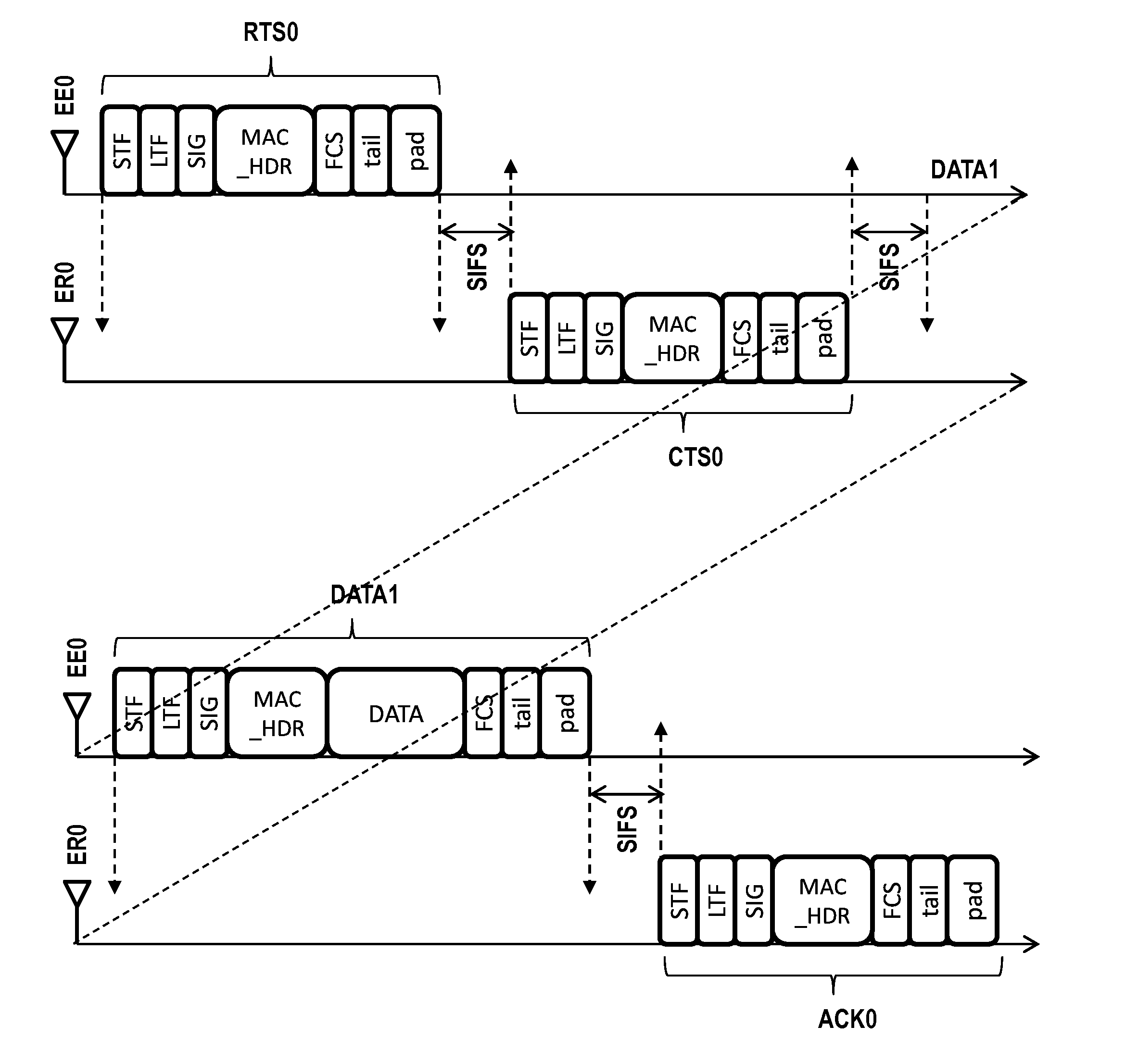
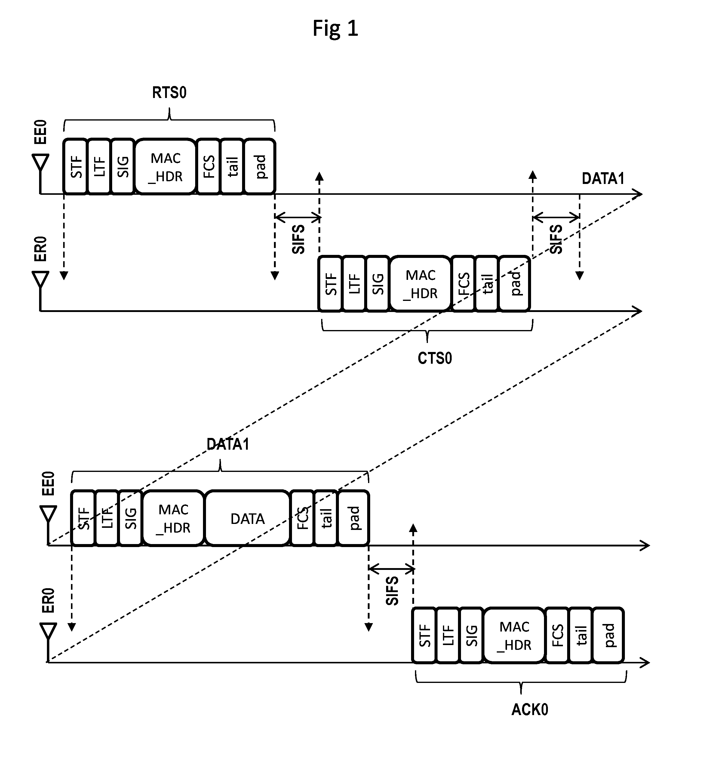
[0084]The structure of a data frame DATA1 and the structure of the control frames RTS0, CTS0 and ACK0, according to the prior art, have been presented further above with reference to FIG. 1.

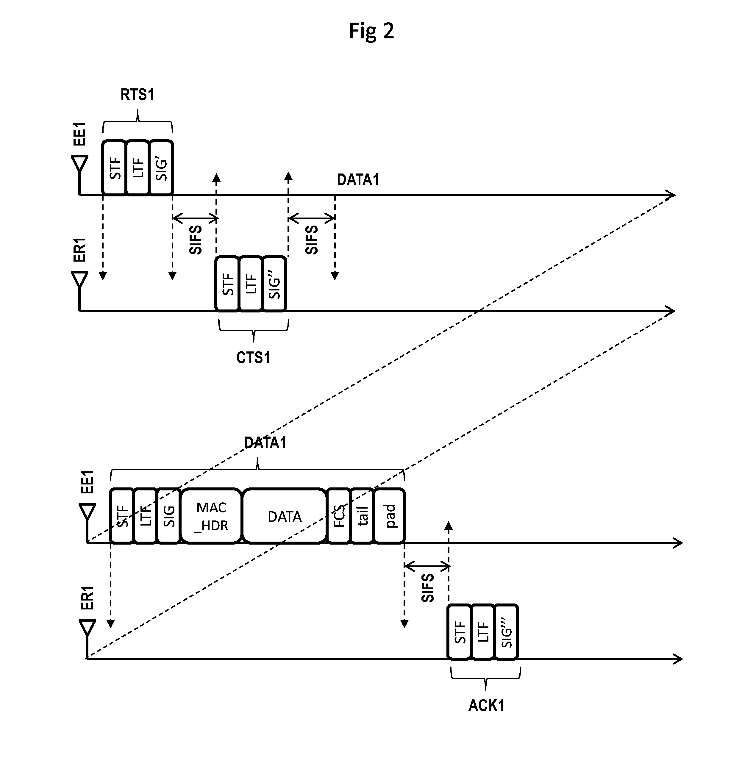
[0085]FIG. 2 shows the structure of a data frame and the structure of various control frames, according to an embodiment of the invention.

[0086]The sequence, illustrated as an example, between control frames and data frame remains unchanged in relation to the prior art and has been described with reference to FIG. 1.

[0087]The co...


PUM


Abstract

A method is provided for transmitting a control frame from a emitting entity to a receiving entity. The control frame includes what is called a “first layer” header field intended to convey information relating to a first layer. The method includes a modulation step employing a first modulation technique, and, before the modulation step, a step of inserting information relating to a second layer into the first layer header field.

Description

1. FIELD OF THE INVENTION[0001]The field of the invention is that of communication systems using a radio, electrical or optical transmission channel, and more particularly that of the management of a channel using control frames, when said channel is shared between a plurality of transmitting or receiving entities.2. PRIOR ART[0002]In radio communication systems, powerline communication and wireless optical communication, the transmission channel is a shared resource that is perturbed by interference between the various transmitting and receiving entities that share the channel, and by collisions between the various data frames passing through the channel. To make the data frame interchanges more reliable, so-called “control” frames are interchanged between the transmitting and receiving entities, before and after a data frame interchange.[0003]The data frames and the control frames are in the same format. FIG. 1 illustrates the composition of a frame, taking as a basis the IEEE 802...

Claims


Application Information

Patent Timeline
IPC IPC(8): H04W72/04
CPCH04W72/0406H04L1/0079H04L1/1685H04W84/12H04W72/20
Inventor CHRISTIN, PHILIPPECARIOU, LAURENT
Owner ORANGE SA (FR)
Learn More