Apparatus And Method For Hadron Beam Verification

a technology of apparatus and method, applied in the field of charged hadron therapy, can solve the problems of reducing the efficiency of treatment facilities in terms of number of treatments, and the device is not suitable for measuring the beam range of particle beams

Active Publication Date: 2015-05-21
ION BEAM APPL
View PDF4 Cites 2 Cited by
  • Summary
  • Abstract
  • Description
  • Claims
  • Application Information

AI Technical Summary

Benefits of technology

[0007]The invention is related to an apparatus for hadron beam verification as disclosed in the appended claims. The apparatus of the invention allows the verification of at least the beam range and the spot size and spot position without replacing the apparatus or changing its position.

Problems solved by technology

Such long verification times are reducing the efficiency of the treatment facility in terms of the number of treatments that can be performed per day.
This device is not suitable for

Method used


Image

  • Apparatus And Method For Hadron Beam Verification
  • Apparatus And Method For Hadron Beam Verification
  • Apparatus And Method For Hadron Beam Verification

Examples


first embodiment

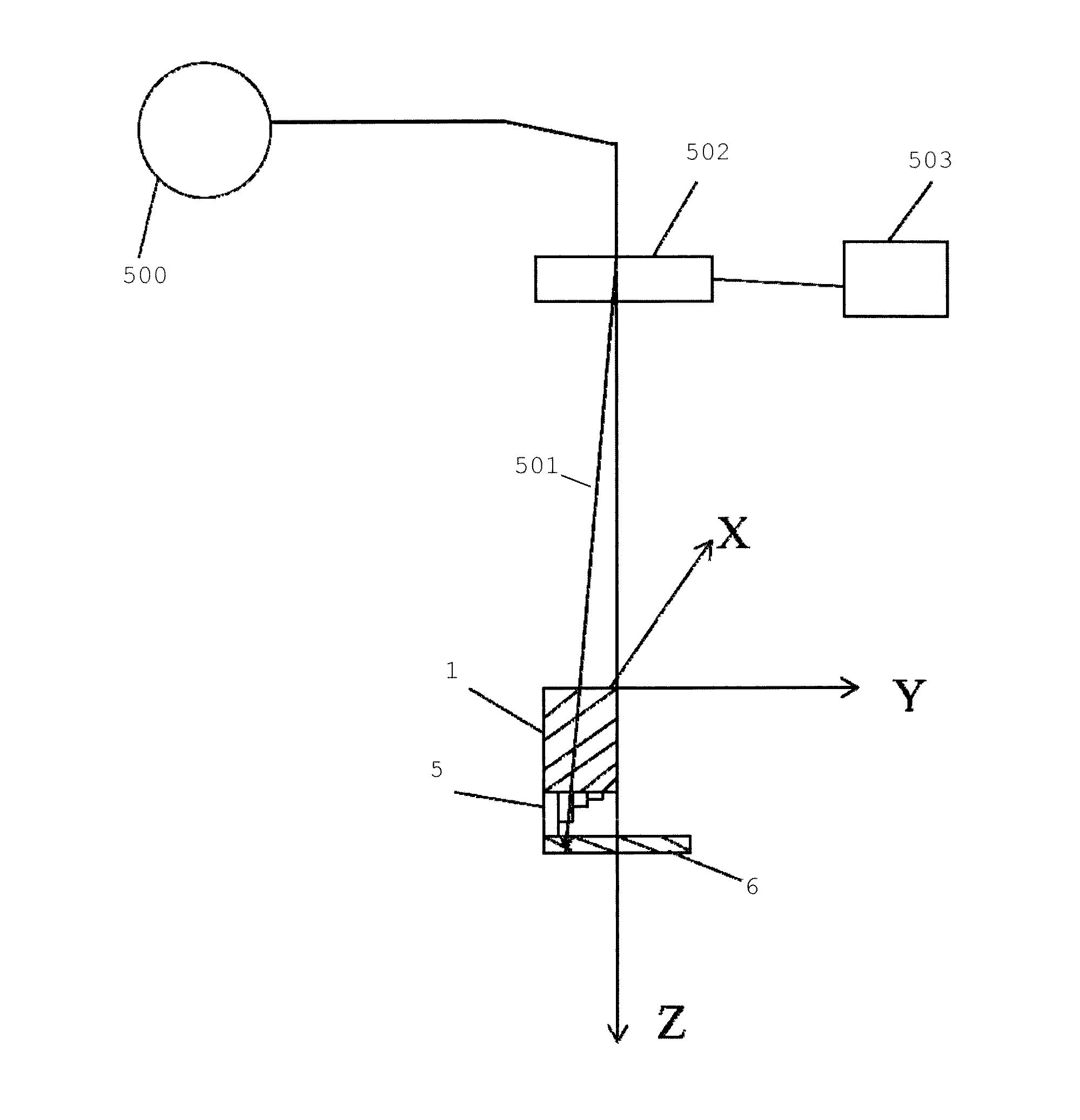
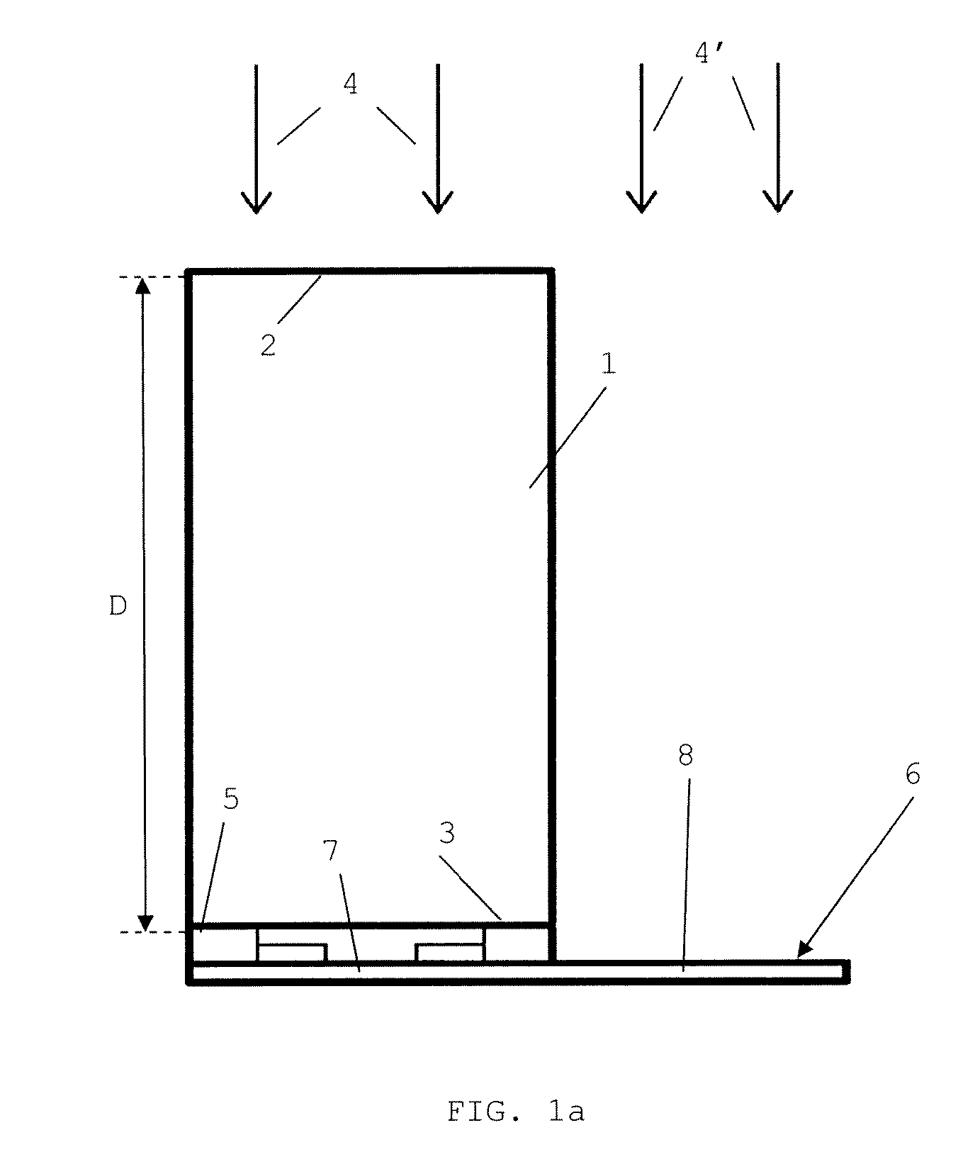
[0056]The following description refers to a device for proton beam verification. The device is however suitable for verification of any other type of hadron beam (ion beam e.g.). FIG. 1 is a schematic representation of a device according to the invention. It comprises three basic components:[0057]a main degrader element 1: this is a volume of material with known proton beam energy degrading characteristics. The main degrader element has mutually parallel surfaces 2 and 3. The main degrader element is suitable for being positioned with respect to a pencil beam irradiation installation so that pencil beams may be aimed at the parallel surfaces 2 and 3 (i.e. the beam passes through the degrader element from one surface to the other; possibly the beam is perpendicular to both surfaces). The main degrader element 1 has a predefined thickness D. Preferably the degrader element 1 is a rectangular block of PMMA or another suitable material with a known water-equivalent thickness. Alternativ...

second embodiment

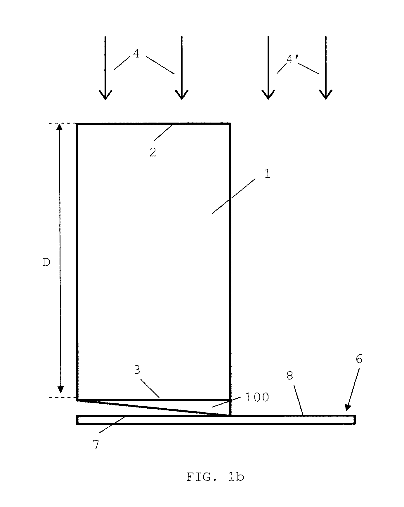
[0062] the multiple thickness degrader element is a wedge degrader element 100, as illustrated in FIG. 1b. The wedge element has a continuously changing thickness from one side to the other. The wedge element is therefore another example of the multiple thickness degrader element referred to in the appended claims. In the wedge element, the degrader portions referred to in the claims are formed by cross-sections of different thickness.

[0063]The main degrader element 1 has a thickness D that is designed with respect to a pre-defined proton beam energy. For this energy the predicted maximum of the Bragg peak (based on the beam energy and degrader material characteristics) is situated approximately at the end plane of the main degrader 1, and preferably downstream of said end plane (seen in the direction of the beam). When the multiple thickness element 5 or the wedge element 100 is placed after the main degrader element, preferably in contact with said element, i.e. forming an extensi...


PUM


Abstract

The present invention is related to an apparatus and method for hadron beam verification. The apparatus allows to verify a number of different characteristics in a brief time span. The apparatus comprises at least one main degrader element and associated therewith a multiple thickness degrader element. The latter may comprise a number of patches of beam degrading material, the patches having constant but mutually different thicknesses. Alternatively, it may be a wedge-shaped element. By aiming a pencil beam at the various thicknesses, data points can be obtained which allow to make an estimation of the beam range. In addition to this, the apparatus comprises a zone where no degrader material is present, and where a measurement of the spot size can be obtained, without moving or replacing the apparatus.

Description

FIELD OF THE INVENTION[0001]The invention is related to the field of charged Hadron therapy. More particularly, the invention is related to the verification of a hadron beam used in the pencil beam scanning technique.STATE OF THE ART[0002]In current proton beam facilities, the Pencil beam scanning technique (PBS) involves the irradiation of separate spots in a target, each spot having a predefined position and depth, with a pre-defined dose being prescribed for each spot. In each treatment room of the facility, various characteristics of the delivered beam are subjected to a daily verification routine. These characteristics are:[0003]Beam range: the position of the Bragg peak at a given beam energy in a given target, measured usually with a water phantom or multi-layer ionization chamber,[0004]spot position and spot size, measured usually by a suitable 2D-detector, for example an array of ionization chambers or a scintillator screen equipped with a CCD camera,[0005]the deposited dos...

Claims


Application Information

Patent Timeline
IPC IPC(8): A61N5/10
CPCA61N5/1049A61N2005/1061A61N5/1071A61N5/1078A61N5/1075A61N2005/1076A61N2005/1087
Inventor DESSY, FREDERICCLAEREBOUDT, YVES
Owner ION BEAM APPL
Why Eureka
Try Eureka