Connector

a technology of connectors and connectors, applied in the field of connectors, can solve the problems of damage to the end part of the shield shell of the wire, and achieve the effect of reducing the load on the wire and preventing the increase in the number of connector components

Active Publication Date: 2015-05-28
SUMITOMO WIRING SYST LTD
View PDF3 Cites 18 Cited by
  • Summary
  • Abstract
  • Description
  • Claims
  • Application Information

AI Technical Summary

Benefits of technology

[0007]The invention is directed to a connector to be mounted on a case of a device. The connector includes a housing is made of synthetic resin and a wire is drawn out from the housing, a shield bracket which is made of metal and fixed to the case in a state where the shield bracket covers the housing and the wire is drawn out through an opening. A seal is accommodated in the housing and seals between the housing and the wire. A back retainer made of synthetic resin is mounted in the housing to retain the seal and is arranged in the shield bracket in a state where the wire is supported. A wire protecting portion is provided on the back retainer at a distance from the wire and projects out from an opening of the shield bracket. Accordingly, a part for supporting the wire is arranged in the shield bracket and the wire protecting portion projects out through the opening of the shield bracket. Thus, the wire can be bent without being brought into contact with the shield bracket, thereby preventing the wire from being damaged by contact with the shield bracket.
[0008]The wire can be bent about a support in the shield bracket. Thus, the wire can be bent at a moderate angle and a load on the wire can be reduced.
[0009]The wire protecting portion may be integral or unitary with the back retainer. Thus, an increase in the number of components of the connector can be prevented since it is not necessary to provide a separate wire protecting portion in addition to the back retainer.
[0010]The wire protecting portion may be provided along an edge of the opening of the shield bracket. Thus, the wire contacts the wire protecting portion regardless of the bending direction of the wire, and the shield bracket will not damage the wire.
[0011]The housing may include a wire draw-out portion from which the wire is drawn out backward, and a front stop may be provided on an edge of the opening of the shield bracket that contacts a rear end of the wire draw-out portion. The front stop projects inward and stops the shield bracket in front with respect to the housing. This design prevents the wire from being damaged by the front stop because the wire protecting portion is on the back retainer and the front stop of the shield bracket is arranged around the wire draw-out portion from which the wire is drawn out to.

Problems solved by technology

However, if the part for supporting the wire is arranged in the shield shell, the wire contacts an end part of the shield shell and can be damaged when being bent.

Method used


Image

  • Connector
  • Connector
  • Connector

Examples


Embodiment Construction

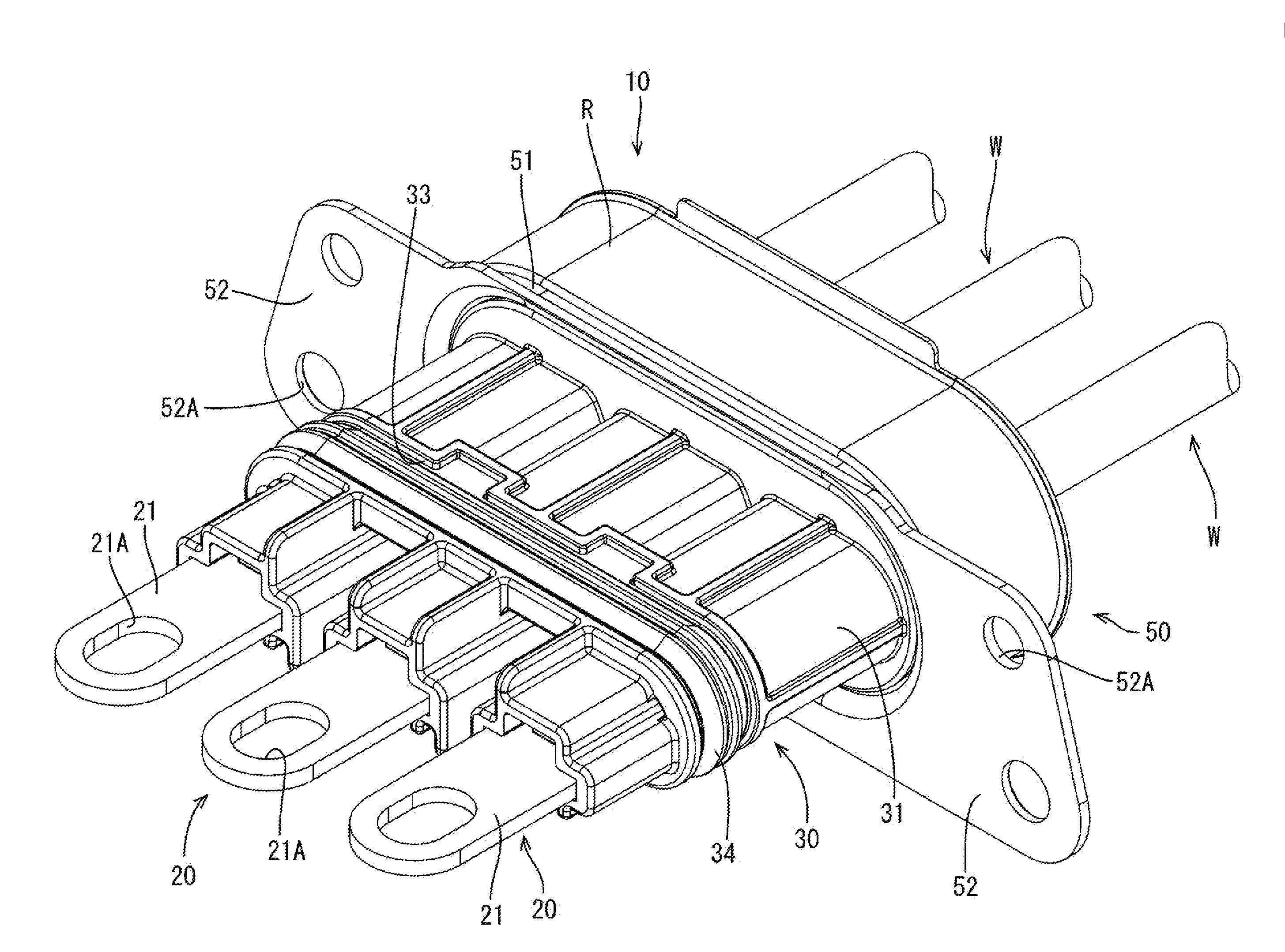
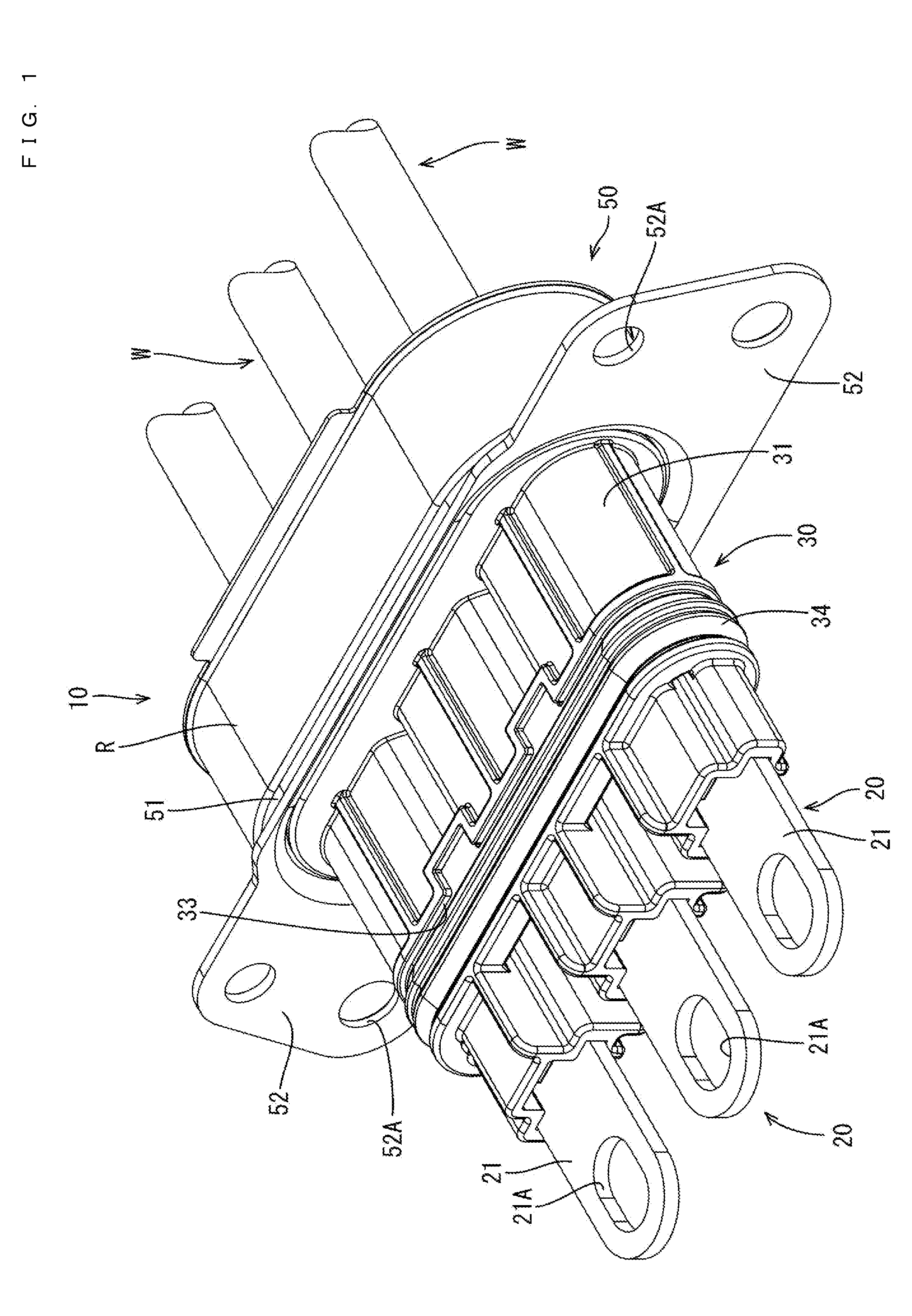
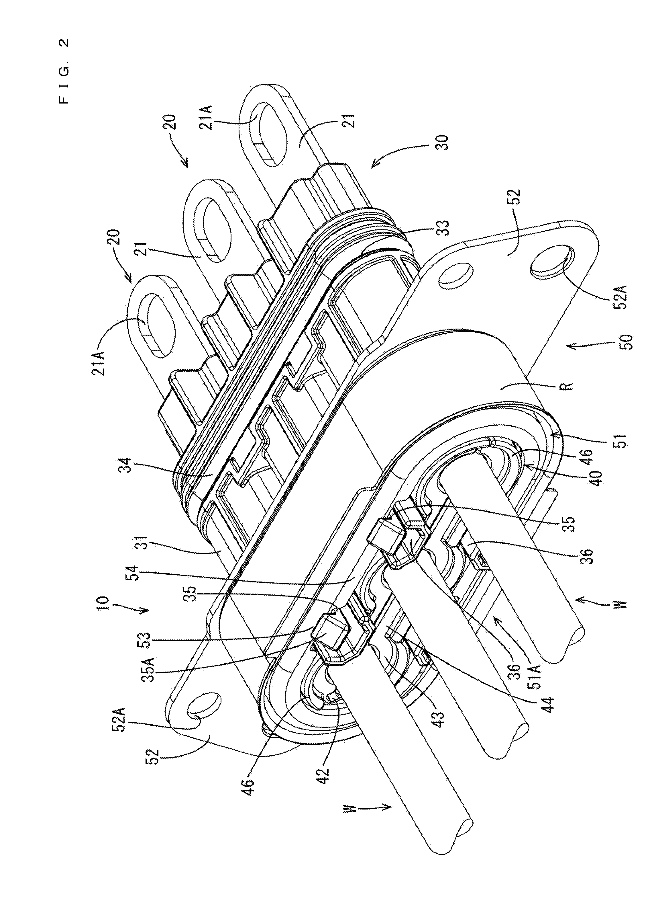
[0022]A connector in accordance with an embodiment of the invention is illustrated in FIGS. 1 to 10 and is identified generally by the numeral 10. The connector 10 is to be mounted on a metal case C of a device to be installed in a vehicle in this embodiment. In the following description, a vertical direction is based on that in FIG. 3 and a lateral direction is based on that in FIG. 3. Further, a front-back direction is based on a lateral direction in FIGS. 4 and 5 and an end to be mounted in the case C is referred to as the front.

[0023]As shown in FIGS. 4 and 5, the connector 10 includes terminals 20 that are connected to ends of wires W, a housing 30 that holds the terminals 20 so that the wires W are drawn out backward from the housing, and a shield bracket 50 that is fixed to the case C while covering a rear part of the housing 30.

[0024]Each terminal 20 is formed by press-working a metal plate material. Further, as shown in FIGS. 1, 5 and 6, each terminal 20 includes a device-s...


PUM


Abstract

A connector (10) to be mounted on a case (C) of a device includes a resin housing (30). A shield bracket (50) is fixed to the case (C) to cover the housing (30) and wires (W) are drawn out through a rear opening (51A). Rubber plugs (24) are accommodated in cavities (37) in the housing (30) and seal between inner surfaces of the cavities (37) and the wires (W). A resin back retainer (40) is mounted in a wire draw-out portion (32) of the housing (30) to be arranged in a tubular portion (51) of the shield bracket (50) with the wires (W) supported and retains the rubber plugs (24). Wire protecting portions (46) are provided at positions of the back retainer (40) at a distance from the wires (W) and project back from the rear end opening (51A) of the shield bracket (50).

Description

BACKGROUND[0001]1. Field of the Invention[0002]The invention relates to a connector.[0003]2. Description of the Related Art[0004]Japanese Unexamined Patent Publication No. 2011-175775 discloses a connector to be mounted on a case of a device. The connector includes a housing made of synthetic resin and a wire is drawn out backward from the housing. A shield shell is fixed to the case and covers the housing. A seal is accommodated in a rear part of the housing for sealing between the wire and the housing, and a retainer is mounted in the housing to prevent the seal from coming out backward. The seal retainer is formed so that a part for supporting the wire projects back from an opening on the rear end of the shield shell, and the wire is drawn out backward from this part for supporting the wire.[0005]The wire is bent at a steep angle if a space between the connector and a peripheral device arranged behind the connector is narrow. Thus, it is required to shorten a dimension of a part ...

Claims


Application Information

Patent Timeline
Patent Type & Authority Applications(United States)
IPC IPC(8): H02G15/007H02G15/013
CPCH02G15/013H02G15/007H02G3/22H01R13/4223H01R13/4367H01R13/5208H01R13/748
Inventor TANAKA, YUKARI
Owner SUMITOMO WIRING SYST LTD
Why Eureka
Try Eureka