Supercharge Your Innovation With Domain-Expert AI Agents!

Tank Vent Filter With Downpipe

a technology of tank vent filter and downpipe, which is applied in the direction of moving filter element filter, filtration separation, separation process, etc., can solve the problems of limited functionality of tank vent filter and inability to understand, and achieve the effect of compact design

Inactive Publication Date: 2015-05-28
MANN HUMMEL GMBH
View PDF2 Cites 3 Cited by
  • Summary
  • Abstract
  • Description
  • Claims
  • Application Information

AI Technical Summary

Benefits of technology

The objective of this patent is to create a tank vent filter that is more compact.

Problems solved by technology

The tank vent filter is therefore described in this mounting position using the positional terms “upper end, lower end, above, etc.” Moreover, the term “tank vent filter” must not be understood such that the functionality of the tank vent filter is limited to tank ventilation.

Method used


Image

  • Tank Vent Filter With Downpipe
  • Tank Vent Filter With Downpipe
  • Tank Vent Filter With Downpipe

Examples


Embodiment Construction

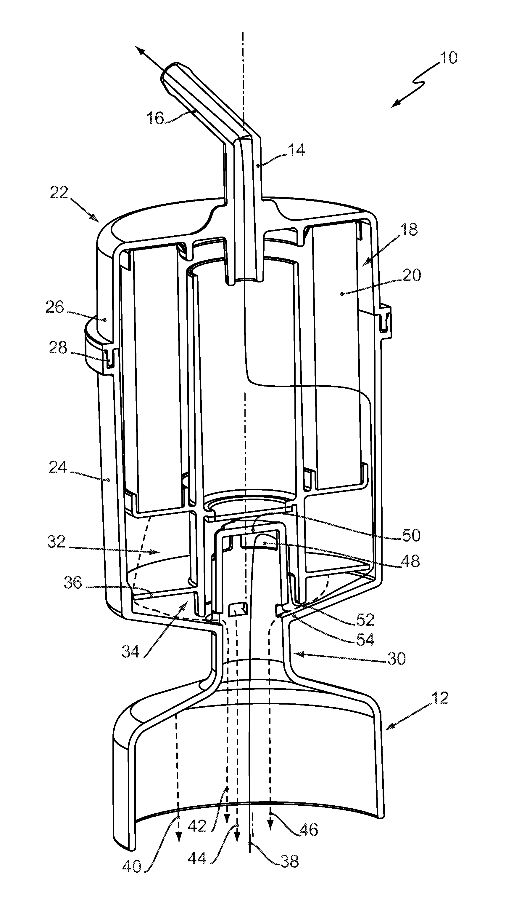
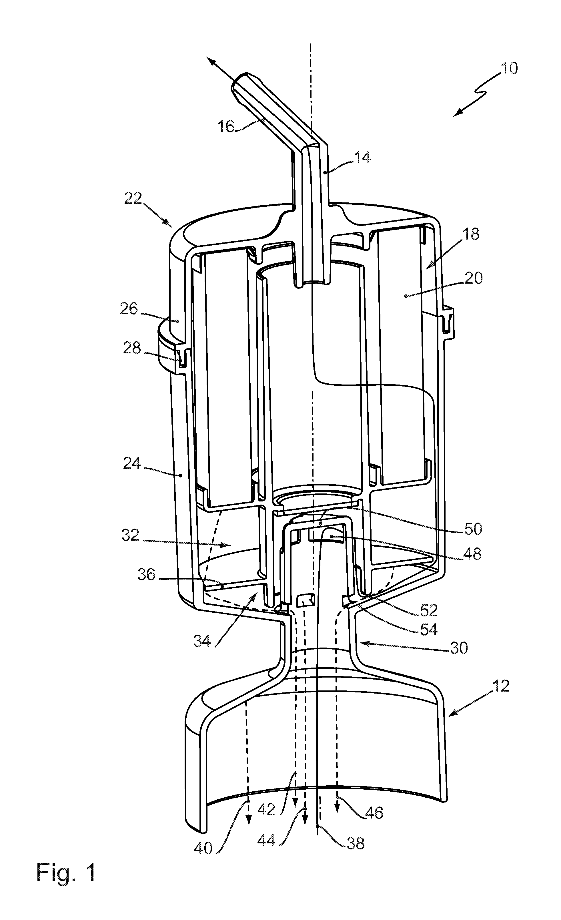
[0050]FIG. 1 shows a first tank vent filter 10. The tank vent filter 10 is used to vent and bleed a tank (not shown). The tank vent filter 10 has an air inlet 12 and an air outlet 14. The air outlet 14 can be connected to the tank via a connection piece 16. The air outlet 14 is used to attach the tank vent filter 10 to a motor vehicle.

[0051]The tank vent filter 10 has a filter element 18 with a first filter 20. The first filter 20 has a star-shaped folded filter material for filtering particles. As a result, the tank contents are kept free of dirt that would otherwise be sucked into the tank as the level of the tank contents drops.

[0052]The tank vent filter 10 has a housing 22 with a lower housing half 24 and an upper housing half 26. The two housing halves 24, 26 are connected to each other at a radial joint 28, for example by a friction-welded seam. The first tank vent filter 10 can thus be produced in an especially cost-effective manner.

[0053]The air inlet 12 is embodied in the l...


PUM

PropertyMeasurementUnit
permeableaaaaaaaaaa
flow resistanceaaaaaaaaaa
diameteraaaaaaaaaa

Abstract

The invention relates to a tank vent filter (70) that guides tank contents that have inadvertently reached the tank vent filter (70) through a downpipe (80) past a first filter (78) of the tank vent filter (70). A contamination of the first filter (78) is thus prevented by means of a space-saving arrangement. The downpipe (80) and the first filter (78) are preferably arranged rotationally symmetrically around the longitudinal axis of the tank vent filter (70) in order to achieve an especially compact design of the tank vent filter (70).

Description

CROSS-REFERENCE TO RELATED PATENT APPLICATIONS[0001]This application claims the benefit of German Application No. 102013019331.1, filed Nov. 20, 2013, which is incorporated herein by reference in its entirety.TECHNICAL FIELD[0002]The invention relates to a tank vent filter, particularly for a motor vehicle.BACKGROUND[0003]It is known to use tank vent filters in order to clean the supply air flowing into the tank, particularly to dehumidify the air flowing into the tank and to filter particles out. Such tank vent filters are known, for example, from US 2007 / 0175524 A1, US 2010 / 0224069 A1 and US 2003 / 0145728 A1.[0004]A tank vent filter is known from U.S. Pat. No. 2,603,308 that has, on its air outlet side, a chamber that is bordered by two plates with small through recesses in order to prevent contamination of a filter element in the tank vent filter as a result of fuel “sloshing” out of the tank.[0005]Moreover, EP 2 607 136 A1 discloses a tank vent filter having a mechanically actuat...

Claims


Application Information

Patent Timeline
Patent Type & Authority Applications(United States)
IPC IPC(8): B01D35/027B60K15/035
CPCB01D35/027B60K2015/03236B60K2015/03509B60K15/03504B01D2279/35B01D46/2403B01D46/62B01D46/2411
Inventor HOLZWARTH, MARCELSCHMID, DANIELVOGT, CHRISTIAN
Owner MANN HUMMEL GMBH
Features
  • R&D
  • Intellectual Property
  • Life Sciences
  • Materials
  • Tech Scout
  • Unparalleled Data Quality
  • Higher Quality Content
  • 60% Fewer Hallucinations
Learn More