Display control device and display control method

a control device and display control technology, applied in the direction of television systems, selective content distribution, instruments, etc., can solve the problems of deteriorating display quality of on-screen display images, inability to smoothly move and move on-screen display images, etc., to achieve the effect of suppressing the deterioration of display quality of on-screen displayed images

Inactive Publication Date: 2015-05-28
PANASONIC INTELLECTUAL PROPERTY MANAGEMENT CO LTD
View PDF5 Cites 13 Cited by
  • Summary
  • Abstract
  • Description
  • Claims
  • Application Information

AI Technical Summary

Benefits of technology

[0006]The present invention has been devised in order to solve the problems described above and it is an object of the present invention to provide a display control device and a display control method capable of suppressing deterioration in display quality of an on-screen displayed image.

Problems solved by technology

However, when the frame rate is reduced, if a moving image is on-screen displayed and the frame rate is gradually increased, the on-screen display image does not smoothly move and moves at intervals and display quality of the on-screen display image is deteriorated.

Method used


Image

  • Display control device and display control method
  • Display control device and display control method
  • Display control device and display control method

Examples


first embodiment

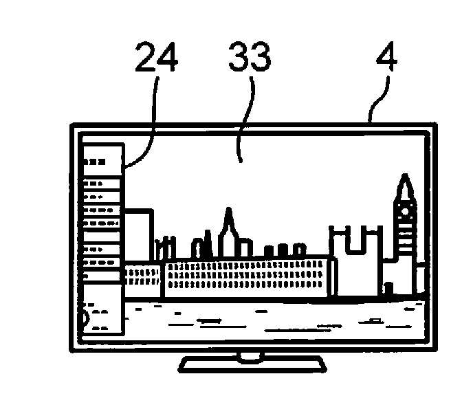
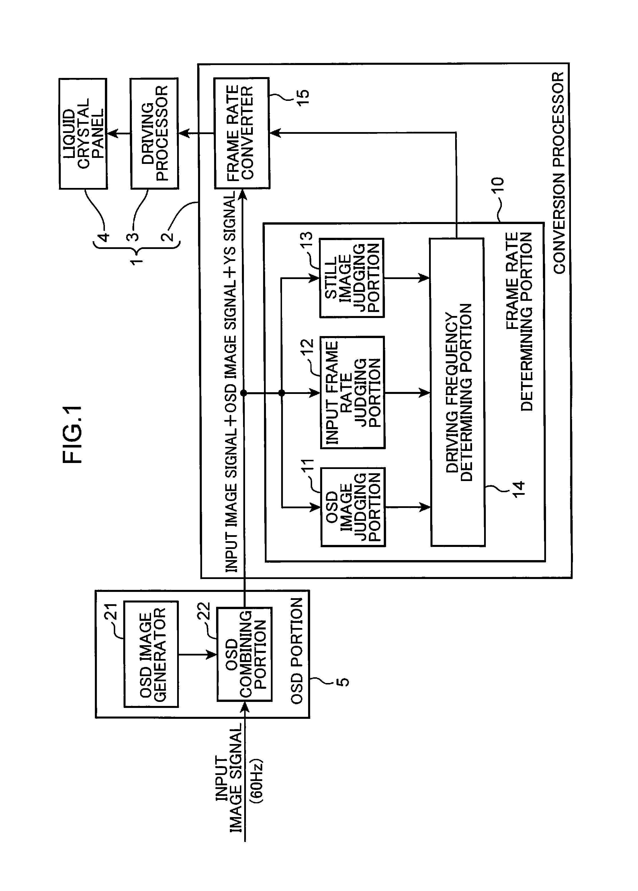
[0021]FIG. 1 is a block diagram of a configuration of a display device including the first embodiment of a display control device and a configuration of an on-screen display portion (OSD portion). A display device 1 shown in FIG. 1 includes a conversion processor 2, which is the first embodiment of the display control device, a driving processor 3, and a liquid crystal panel (a display portion) 4. An OSD portion 5 shown in FIG. 1 includes an on-screen display (OSD) image generator 21 and an on-screen display (OSD) combining portion 22.

[0022]Although not shown in the figure, the liquid crystal panel 4 includes gate lines extending in the horizontal direction, source lines extending in the vertical direction, switching elements, and pixels. The switching elements and the pixels are arranged in a matrix at intersections of the source lines and the gate lines. One scanning line is configured from pixels in one line in the horizontal direction.

[0023]Driving signals corresponding to the p...

second embodiment

[0044]FIG. 6 is a block diagram showing a configuration of a display device including the second embodiment of the display control device and a configuration of an OSD portion. In FIG. 6, the same components as the components shown in FIG. 1 are denoted by the same reference symbols. A display device 1a shown in FIG. 6 includes a conversion processor 2a, which is the second embodiment of the display control device, instead of the conversion processor 2 in the display device 1 shown in FIG. 1. In the following description of the second embodiment, differences from the first embodiment are mainly described.

[0045]As shown in FIG. 6, the conversion processor 2a includes a high definition multimedia interface (HDMI) acquiring portion 16 in addition to the frame rate determining portion 10 and the frame rate converter 15 included in the conversion processor 2 shown in FIG. 1. An OSD portion 5a shown in FIG. 6 includes an HDMI output portion 23 in addition to the OSD image generator 21 and...

third embodiment

[0047]FIG. 7 is a block diagram showing a configuration of a display device including the third embodiment of the display control device and a configuration of an OSD portion. In FIG. 7, the same components as the components shown in FIG. 1 are denoted by the same reference symbols. A display device 1b shown in FIG. 7 includes a conversion processor 2b, which is the third embodiment of the display control device, instead of the conversion processor 2 in the display device 1 shown in FIG. 1 and further includes a camera 6. In the following description of the third embodiment, differences from the first embodiment are mainly described.

[0048]As shown in FIG. 7, the conversion processor 2b includes a frame rate determining portion 10a instead of the frame rate determining portion 10 included in the conversion processor 2 shown in FIG. 1. The frame rate determining portion 10a includes a driving frequency determining portion 14a instead of the driving frequency determining portion 14 in ...


PUM


Abstract

A display control device includes a determining portion determining a frame rate in displaying a frame image on a display portion as a determined frame rate; and a converter converting a present frame rate into the determined frame rate when the determined frame rate is different from the present frame rate. The determining portion determines, based on information about an OSD image, whether the determined frame rate is set to a frame rate identical to or higher than the present frame rate, and when determining that the determined frame rate is set to the frame rate higher than the present frame rate, determines the frame rate as the determined frame rate to display the frame image at the determined frame rate starting from a frame image which is K frames after a currently displayed frame image, where K is an integer not less than 1 and not more than 10.

Description

TECHNICAL FIELD[0001]The present invention relates to a display control device and a display control method for controlling display on a display portion that displays frame images.BACKGROUND ART[0002]A display device including a display portion that displays frame images successively switches the frame images displayed on the display portion on the basis of, for example, an input image signal from the outside to display smooth images on the display portion. A frequency for switching the frame images is called frame rate, and 60 Hz is used in general. It has been known a display device that detects whether an input image signal is a signal representing a still image or a signal representing a moving image and switches a frame rate according to a detection result (see, for example, Patent Literature 1).[0003]When the input image signal represents the still image, the device described in Patent Literature 1 reduces the frame rate to reduce power consumption during display. When the inp...

Claims


Application Information

Patent Timeline
Patent Type & Authority Applications(United States)
IPC IPC(8): H04N7/01H04N5/45H04N5/445
CPCH04N7/013H04N5/45H04N5/44543H04N7/0132G09G3/3648G09G5/005G09G2320/103G09G2330/021G09G2340/0435G09G2340/12G09G2354/00H04N7/0127H04N21/440218H04N21/47
Inventor IZUMI, YOSHIKI
Owner PANASONIC INTELLECTUAL PROPERTY MANAGEMENT CO LTD
Why Eureka
Try Eureka