
Handling device for handling a rotor blade mold for producing a rotor blade of a wind turbine

a technology of wind turbine and mold, which is applied in the field of transportation vehicles, can solve the problems of complicated and expensive, difficult displacement, and previously known solutions

Inactive Publication Date: 2015-05-28
WOBBEN PROPERTIES GMBH
View PDF6 Cites 0 Cited by
  • Summary
  • Abstract
  • Description
  • Claims
  • Application Information

AI Technical Summary

Benefits of technology

The patent describes a transport vehicle that can move on two different rail sets and can change direction easily. The vehicle has two sets of wheels, each set for travel on a different rail set. The vehicle can also connect to a rotor blade mold for supplying power and can be recharged while in use. The vehicle has a common drive motor that drives multiple wheels, and each wheel has its own drive to synchronize with the others. The vehicle also has a transmission to reduce the speed of rotation of the wheels and to keep the vehicle lightweight. The round rails are set into a floor, and the wheels are adapted to the rounded shape for safe and easy guidance on the rails. The second rotor blade mold can be easily connected and locked in place with the hinge device.

Problems solved by technology

It is precisely in relation to unwieldy objects like such a long rotor blade mold, however, that displacement is difficult and caution is required to ensure that the rotor blade mold does not knock by mistake against an article in the factory when being moved.
Such previously known solutions are therefore complicated and expensive and in operation require personnel with a great deal of experience and a high level of attentiveness.

Method used


Image

  • Handling device for handling a rotor blade mold for producing a rotor blade of a wind turbine
  • Handling device for handling a rotor blade mold for producing a rotor blade of a wind turbine
  • Handling device for handling a rotor blade mold for producing a rotor blade of a wind turbine

Examples


Embodiment Construction

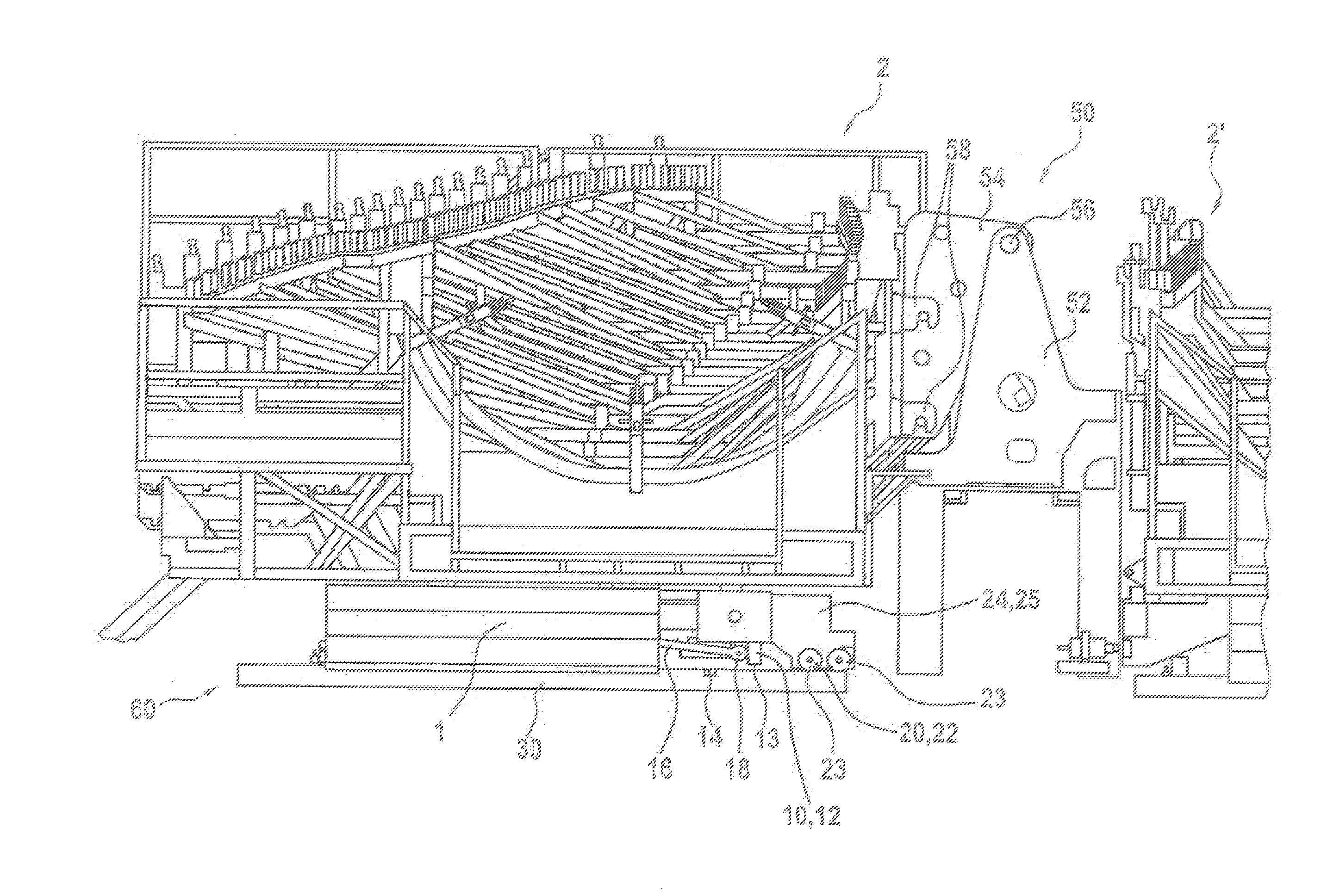
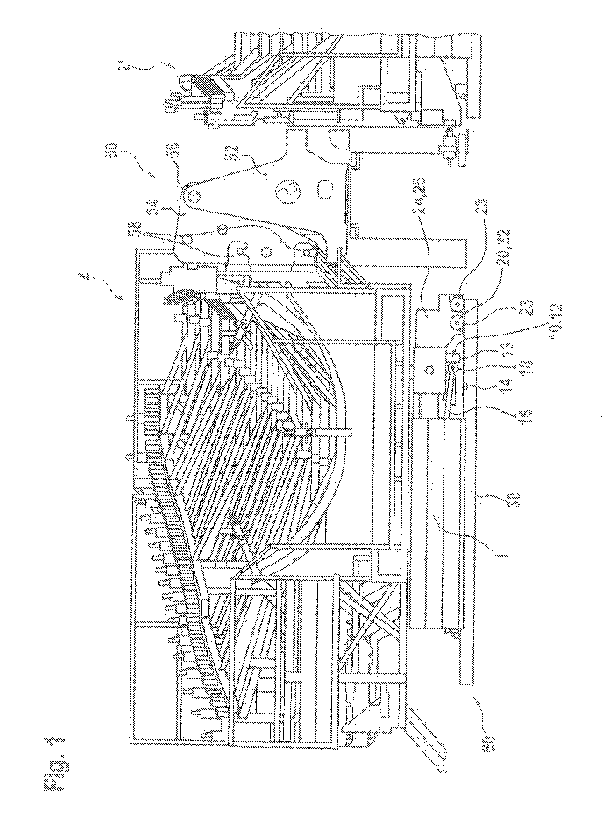
[0052]FIG. 1 shows a perspective view of a transport vehicle 1 with a truss frame structure 2 arranged thereon. The truss frame structure 2 is already roughly adapted to the shape of a rotor blade to be produced and is provided for receiving a rotor blade mold. Such a rotor blade mold is appropriately laid in or placed on that truss frame structure as shown in the drawing. A rotor blade mold provided for the illustrated case is intended for the production of a shell portion of a rotor blade. A further rotor blade mold for a further shell portion would be placed in the truss frame structure 2′ which is only partly shown in FIG. 1. The rotor blade to be produced is finally assembled substantially from those two shell portions. For the sake of simplicity a truss frame structure like the truss frame structure 2 can also be referred to as the mold carrier.

[0053]To fit the two rotor blade shell portions produced in that way together, there is provided a hinge device 50 which has a fixed l...


PUM

PropertyMeasurementUnit
Speedaaaaaaaaaa
Currentaaaaaaaaaa
Transport propertiesaaaaaaaaaa

Abstract

The present disclosure concerns a transport vehicle for handling a rotor blade mold for the production of a rotor blade of a wind power installation or a shell portion of a rotor blade of a wind power installation, adapted for use in a handling apparatus. The handling apparatus includes a first rail set for displacement of the transport vehicle in a first direction, and a second rail set for displacement of the transport vehicle in a second direction. In addition the transport vehicle includes a first wheel set including a plurality of wheels for movement on the first rail set, and a second wheel set including a plurality of wheels for movement on the second rail set.

Description

BACKGROUND[0001]1. Technical Field[0002]The present invention concerns a transport vehicle for handling a rotor blade mold for the production of a rotor blade of a wind power installation. The invention further concerns a handling apparatus which includes such a transport vehicle. Furthermore the invention concerns a process for the production of a rotor blade of a wind power installation.[0003]2. Description of the Related Art[0004]Wind power installations are generally known and usually require at least one and usually three rotor blades which are to be driven by the wind. Modern wind power installations like for example the one shown in FIG. 1 can have a nominal power of several megawatts and require suitably large rotor blades for that purpose. Such rotor blades can nowadays already be of lengths of about 50 m and more. In that respect such a rotor blade is frequently made, at least in a large portion thereof, from glass fiber-reinforced plastic or similar material. A common pos...

Claims


Application Information

Patent Timeline
IPC IPC(8): B29C31/00B65G67/30B60P1/28F03D13/40F03D80/00F03D80/80
CPCB29C31/006B60P1/28B65G2207/14B65G2201/02B65G67/30B29D99/0028Y02P70/50Y02E10/72B29C33/34B61J1/10B29C31/00
Inventor GEORGS, ARNOBIEBL, HERBERTSCHLUTER, RAINER
Owner WOBBEN PROPERTIES GMBH
Learn More