Methods and Apparatus for Remotely Monitoring and/or Controlling a Plumbing System

a technology for remotely monitoring and/or controlling a plumbing system, applied in the field of plumbing systems, can solve the problems of substantial water waste (water loss), commercial establishments also experience wasteful water and energy loss, and wasteful thermal energy waste, so as to reduce water waste and energy waste, and manage water usage.

Active Publication Date: 2015-05-28
ADVANCED CONSERVATION TECH DISTRIBUTION
View PDF26 Cites 34 Cited by
  • Summary
  • Abstract
  • Description
  • Claims
  • Application Information

AI Technical Summary

Benefits of technology

[0001]The present invention is generally directed to plumbing systems and more particularly to operation, control and monitoring of plumbing systems. In preferred examples, the invention is directed to controlling, sensing, and / or monitoring of plumbing systems, such as “on demand” or “on command” type hot water plumbing systems, at a distance remote from the pump or hot water source of the system. In some examples, controlling, monitoring and / or sensing may be done wirelessly, through digital USB, Ethernet or internet connections such as DSL or cable, or at least partially through existing electrical supply lines, such as AC power supply lines, in conjunction with one or more microprocessor in a remote controller component. Such remote controlling, sensing, and / or monitoring systems permits a user to optimize the efficient use of power and water resources towards the attainment of high thermal and economic efficiency.
[0003]In some homes and many commercial establishments, such water loss may be reduced by providing plumbing systems that continuously circulate hot water from a hot water source to the fixture and back to the hot water source. In this arrangement, a supply of hot water is always adjacent to a plumbing fixture despite the remote position of the hot water source.
[0006]Hot water command systems have been developed, such as for example, set forth in U.S. Pat. Nos. 5,277,119; 5,385,161; 5,829,475; 6,962,162; and 8,505,498. The system described in these patents significantly reduces water and energy loss through the use of an on command control. That is, whether a recirculation conduit is utilized or a cold water line is utilized for circulation of water, such circulation is initiated only upon command by a user. Such command may be a manual switch, temperature sensor or the like. Current “on demand” or “on command” hot water systems may utilize a controller component such as a microprocessor to sense parameters such as temperature, pressure, time, and the like and to control components of the hot water system. Such controller components are located on or near the pump or hot water source (such as a hot water heater or boiler) so as to control the activation or deactivation of the pump and / or adjust the temperature of the hot water source according to one or more such parameters.
[0022]A controller component may, for example, reiterate one or more of the above noted steps for providing updated patterns of pump activity, thus enabling pump activation to be continually changed in response to usage of the system.

Problems solved by technology

In a dwelling, a considerable amount of thermal energy may be wastefully dissipated from hot water lines which provide hot water to plumbing fixtures, such as domestic wash basins, showers, dishwashers, washing machines, etc.
Commercial establishments also experience wasteful water and energy losses due to continuously running hot water recirculation systems or for timing or delivering hot water to numerous fixtures, such as in hotels and the like.
In both home and commercial establishments, if cooler water is allowed to run down the drain while waiting for hot water to be delivered to the fixture from a remote hot water source, a substantial waste of water (water loss) may occur.
However, while this arrangement reduces water loss, it is not energy efficient because the array of pipes interconnecting the plumbing fixtures and the hot water source provide a large surface area for thermal radiation to occur.
In addition, continuously running a recirculation pump contributes to additional expense, which may be particularly egregious as the costs of electrical energy continue to increase.
While the installation of such insulation slows the dissipation of heat, no savings occur over an extended period of time in non-circulating systems because intermittent use of hot water through the lines still allows hot water to cool to ambient temperatures.

Method used


Image

  • Methods and Apparatus for Remotely Monitoring and/or Controlling a Plumbing System
  • Methods and Apparatus for Remotely Monitoring and/or Controlling a Plumbing System
  • Methods and Apparatus for Remotely Monitoring and/or Controlling a Plumbing System

Examples


Embodiment Construction

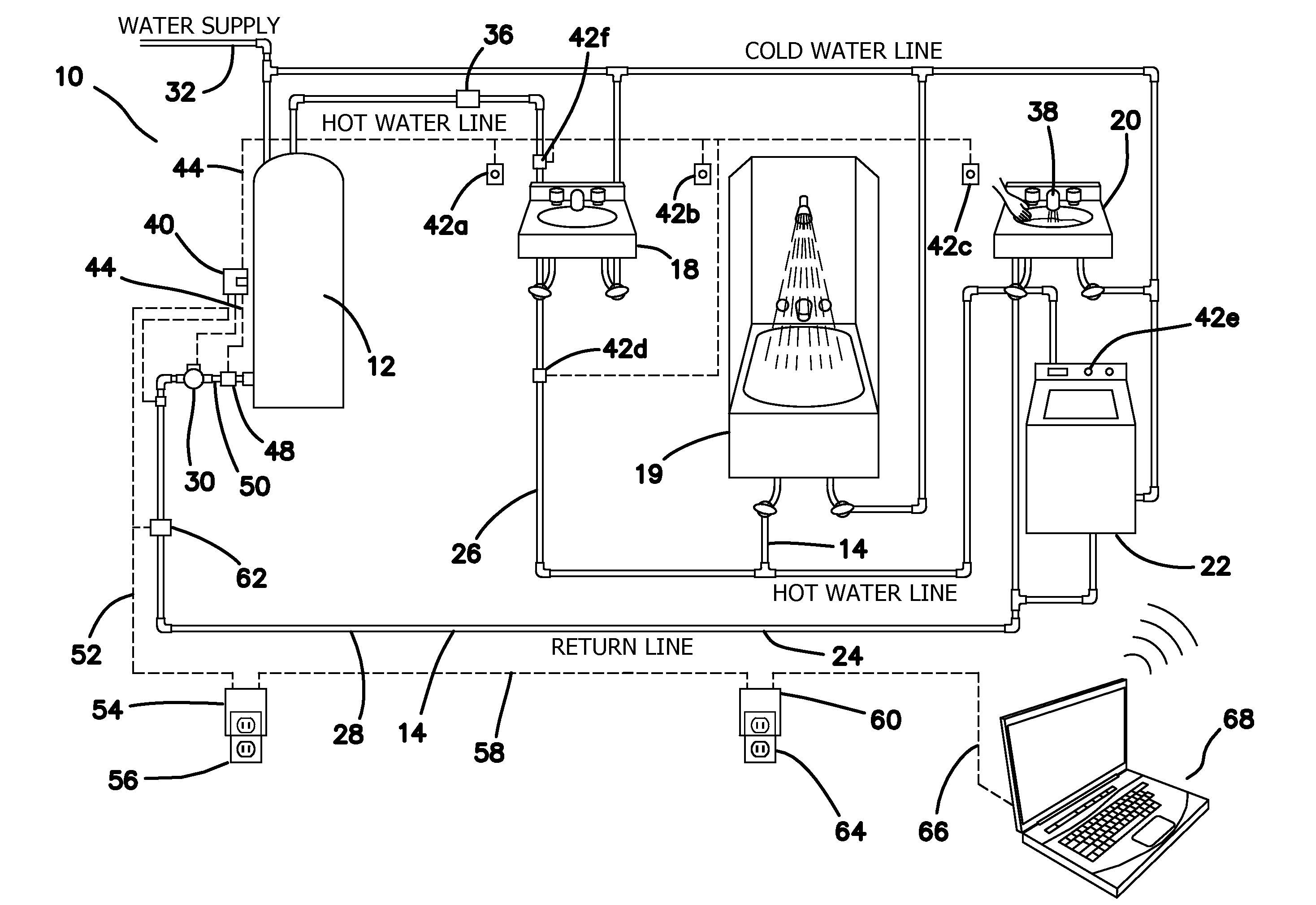
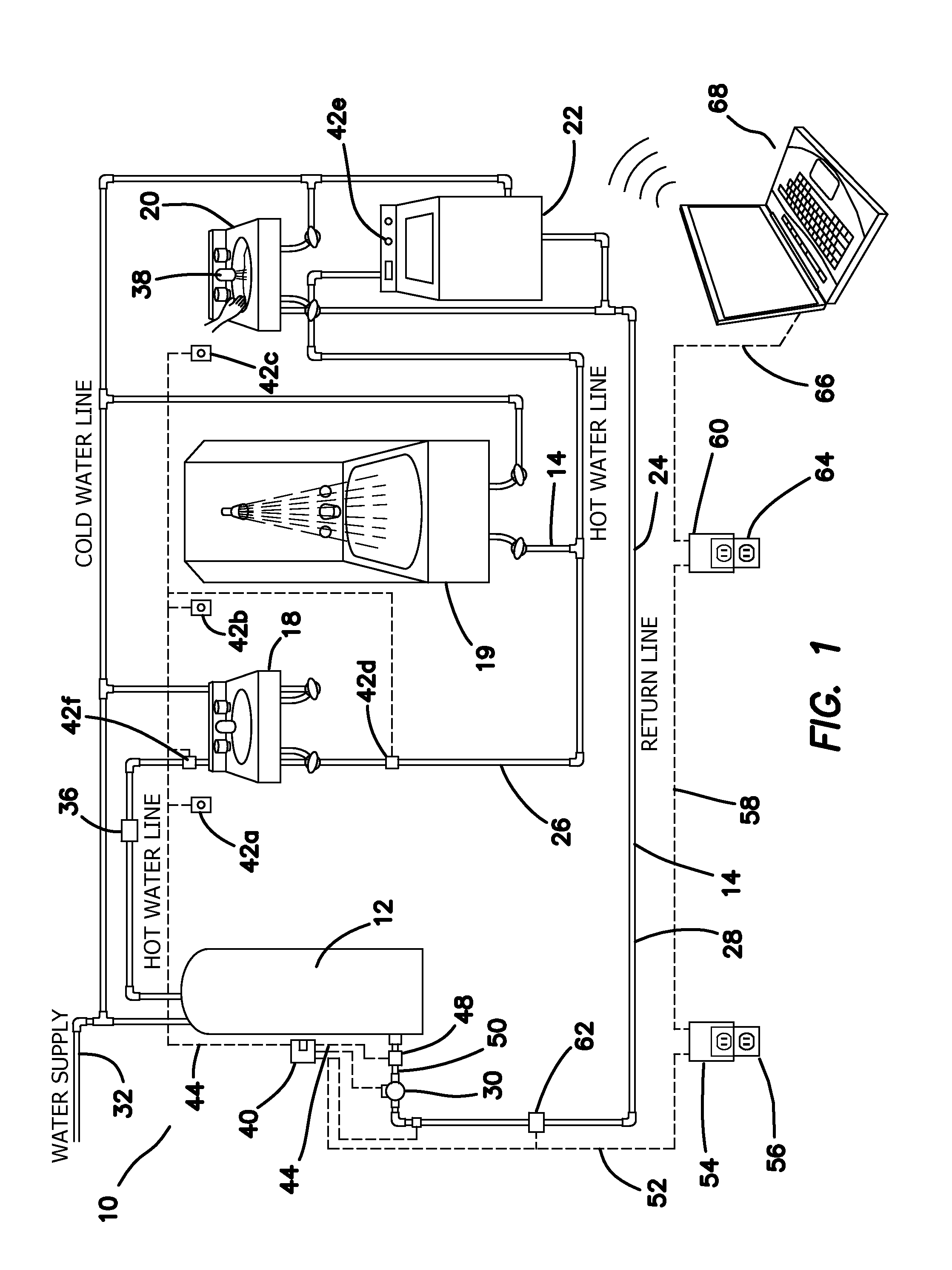
[0038]With reference to FIG. 1, a hot water recirculation system 10 is shown in accordance with the present invention. The system 10 generally comprises various HWS components, which may include a hot water source, for example, a water heater 12, such as a gas, oil, solar, photovoltaic, or electric tanks or tankless heater, interconnected by means of pipes 14 with plumbing fixtures 18, 19, 20, 22, said pipes providing conduit means for enabling circulation of hot water from said hot water source 12 to each plumbing fixture 18, 19, 20 and return to the hot water source 12. The pipes 14 are thus in fluid communication with the hot water source 12 and the plumbing fixtures 18, 19, 20 in such a way as to establish a hot water loop 24.

[0039]More particularly, the pipes 14 may be comprised of a hot water supply line 26 which provides means for transferring hot water from the hot water source (such as a heater) 12 to each of the fixtures 18, 19, 20, 22 and a separate hot water return line ...


PUM


Abstract

Methods and compositions for controlling and monitoring residential and commercial pumping systems. Preferably, the controlling and monitoring functions include a remotely located controller component capable of displaying alerts and / or from which a user may input commands regulating the functioning of the plumbing system. In particularly preferred examples, the plumbing system is an “on command” hot water system in which hot water availability, use and energy efficiencies and conservation are monitored and maximized.

Description

[0001]The present invention is generally directed to plumbing systems and more particularly to operation, control and monitoring of plumbing systems. In preferred examples, the invention is directed to controlling, sensing, and / or monitoring of plumbing systems, such as “on demand” or “on command” type hot water plumbing systems, at a distance remote from the pump or hot water source of the system. In some examples, controlling, monitoring and / or sensing may be done wirelessly, through digital USB, Ethernet or internet connections such as DSL or cable, or at least partially through existing electrical supply lines, such as AC power supply lines, in conjunction with one or more microprocessor in a remote controller component. Such remote controlling, sensing, and / or monitoring systems permits a user to optimize the efficient use of power and water resources towards the attainment of high thermal and economic efficiency.[0002]Water and energy conservation is of utmost importance for b...

Claims


Application Information

Patent Timeline
Patent Type & Authority Applications(United States)
IPC IPC(8): F24D19/10G05B15/02F24H9/20
CPCF24D19/1063G05B15/02F24H9/2028G05B2219/25168F24D17/0031F24D19/1081F24H15/45F24H15/269F24H15/335F24H15/486F24H15/254F24H15/31F24H15/219F24H15/395F24H15/20F24H15/242F24H15/136F24H15/238F24H15/281F04D13/00F04D15/00G05B2219/23051G05B2219/23406
Inventor ACKER, LARRY K.
Owner ADVANCED CONSERVATION TECH DISTRIBUTION
Why Eureka
Try Eureka