Wear Prognosis Method And Maintenance Method

Active Publication Date: 2015-05-28
WIRTGEN GMBH
View PDF7 Cites 30 Cited by
  • Summary
  • Abstract
  • Description
  • Claims
  • Application Information

AI Technical Summary

Benefits of technology

[0010]An object of the invention is to furnish a method tha

Problems solved by technology

Replacement is advisable once the tools reach a specific wear state, since otherwise the ongoing process loses efficiency.
1. Bit replacement because sufficient wear material (in particular carbide metal at the tip) is no longer present. The penetration resistance becomes too high and the efficiency thus decreases (too much frictional loss); the wear is predominantly rotationally symmetrical.
2. Bit holder replacement because the wear limit has been reached (wear occurs on the holder at the contact surface between bit and holder). This wear is usually symmetrical.
3. Rotationally asymmetrical wear on the bit tip and/or bit head due to insufficient rotational movement of the bit during the milling process. The consequences are a poor milling pattern as well as the risk of tool breakage, since the bracing effect of the bit head is lost.
4. The bit holder can furthermore be subject to additional rotationally asymmetrical wear.
In addition, worn and/or broken bits can result in secondary damage to the bit holders, and worn bit holders ca

Method used


Image

  • Wear Prognosis Method And Maintenance Method
  • Wear Prognosis Method And Maintenance Method
  • Wear Prognosis Method And Maintenance Method

Examples


Embodiment Construction

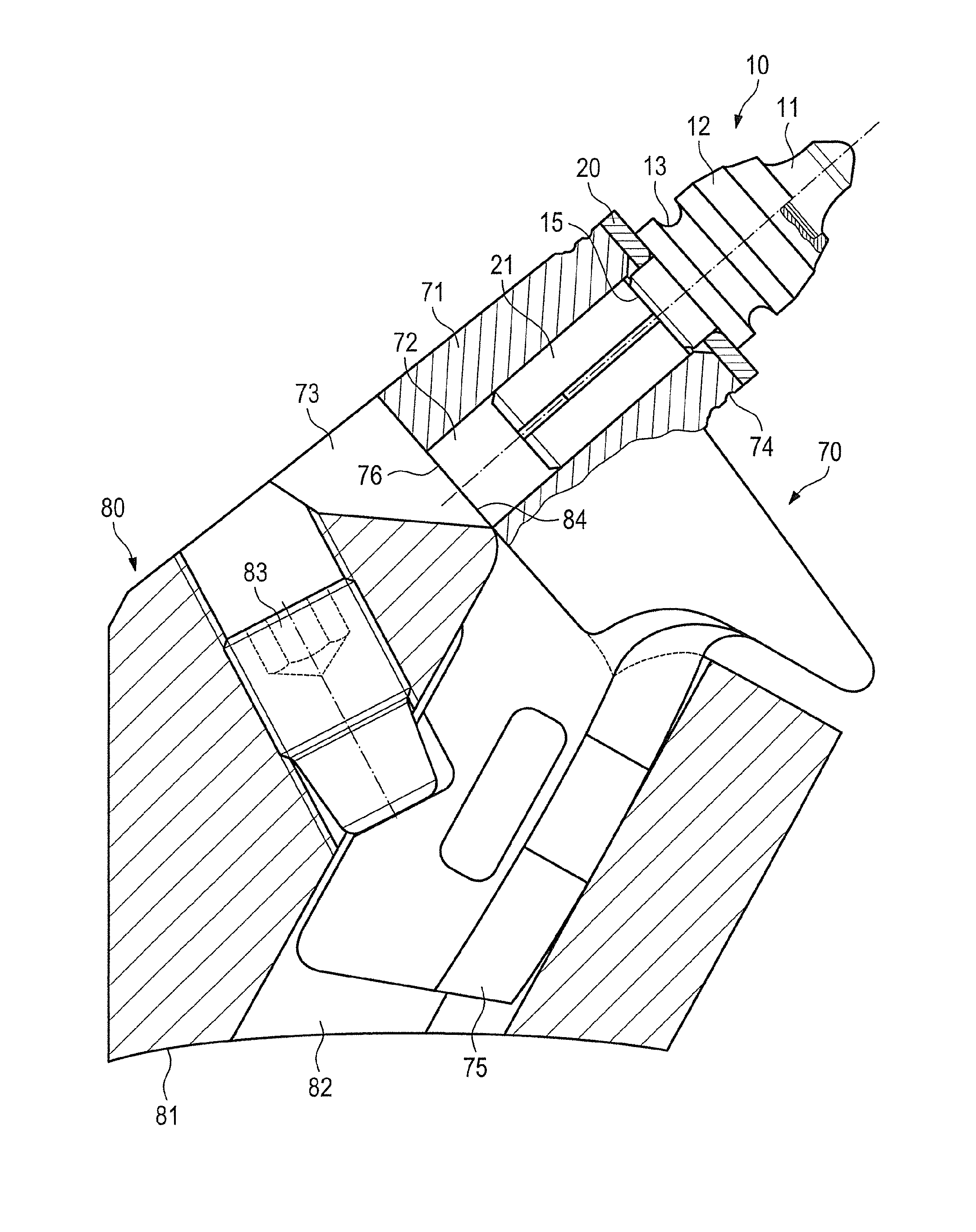
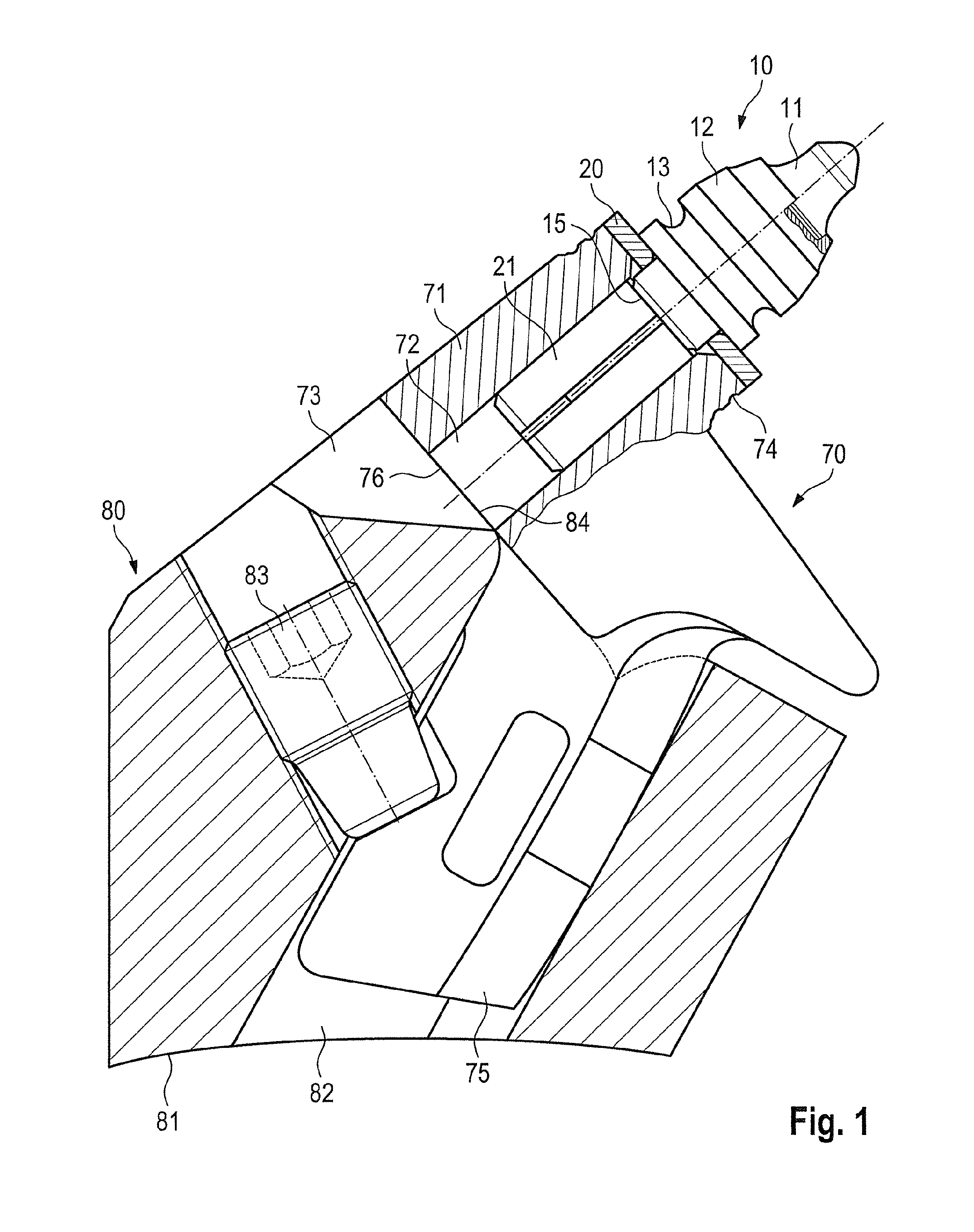
[0035]FIG. 1 shows, as an example of an earth working tool, a bit 10 as known from the existing art and described by way of example in DE 38 18 213 A1. Bit 10 comprises a bit head 12 and a bit shank 15 shaped integrally thereonto. Bit head 12 carries a bit tip 11 made of a hard material, for example of carbide metal.

[0036]This bit tip 11 is usually soldered onto bit head 12 along a contact surface. A circumferential pull-out groove 13 is recessed into bit head 12. This groove serves as a tool receptacle, such that a removal tool can be set in place and bit 10 can be removed from a bit holder 70.

[0037]Bit shank 15 carries a longitudinally slotted cylindrical clamping sleeve 21. This is held on bit shank 15 in lossproof fashion in the direction of the longitudinal dimension of bit 10, but freely rotatably in the circumferential direction. A wear protection washer 20 is arranged in the region between clamping sleeve 21 and bit head 12. In the installed state, wear protection washer 20 ...


PUM


Abstract

A wear prognosis method and a maintenance method for an earth working machine are disclosed, along with an apparatus for performing the method. Provision is made that the current wear state of one or more earth working tools is sensed. The residual wear capacity until the wear limit is reached is then ascertained from the current wear state.

Description

BACKGROUND OF THE INVENTION[0001]In the context of road reconstruction by milling, and the removal of mineral deposits with a surface miner (also by milling), the earth working tools that are used, and in particular the milling bits, are subject to a continuous wear process. Replacement is advisable once the tools reach a specific wear state, since otherwise the ongoing process loses efficiency. A distinction must be made here among a variety of wear states that result in replacement of a milling bit or bit holder:1. Bit replacement because sufficient wear material (in particular carbide metal at the tip) is no longer present. The penetration resistance becomes too high and the efficiency thus decreases (too much frictional loss); the wear is predominantly rotationally symmetrical.2. Bit holder replacement because the wear limit has been reached (wear occurs on the holder at the contact surface between bit and holder). This wear is usually symmetrical.3. Rotationally asymmetrical we...

Claims


Application Information

Patent Timeline
IPC IPC(8): G01N3/56E01C23/088E01C23/12E21C35/00
CPCG01N3/56E01C23/127E01C23/088E21C35/00G01N3/58G05B2219/50308G05B19/4065
Inventor PAULSEN, SVENWAGNER, STEFANBARIMANI, CYRUSHAHN, GUNTER
Owner WIRTGEN GMBH
Why Eureka
Try Eureka