Thermally Insulating Member

a technology of thermally insulating members and components, which is applied in the direction of domestic cooling devices, lighting and heating devices, transportation and packaging, etc., can solve the problems of high transportation cost, high storage cost large space occupation of persons using thermally insulating components, so as to reduce the volume of a plurality improve the thermally insulating effect of thermally insulating components

Active Publication Date: 2015-06-04
BETTER ALLYING DESIGN
View PDF27 Cites 9 Cited by
  • Summary
  • Abstract
  • Description
  • Claims
  • Application Information

AI Technical Summary

Benefits of technology

[0033]The effect achieved by the above technical solution is that the thermally insulating member includes a sheet, with the sheet includes a plurality of flat thermally insulating strips before use, effectively reducing the volume of a plurality of thermally insulating members. On the other hand, the sheet includes a plurality of broken lines, and each broken line includes a plurality of slits. A thermally insulating strip can be defined between two adjacent broken lines, such that the sheet is stretched outward

Problems solved by technology

Thus, the conventional thermally insulating member 9 occupies a considerable space in storage or during transportation.
Particularly, the large volume of the conventional thermally insulating member 9 results in a high transportation cost and causes high storage costs

Method used


Image

  • Thermally Insulating Member
  • Thermally Insulating Member
  • Thermally Insulating Member

Examples


first embodiment

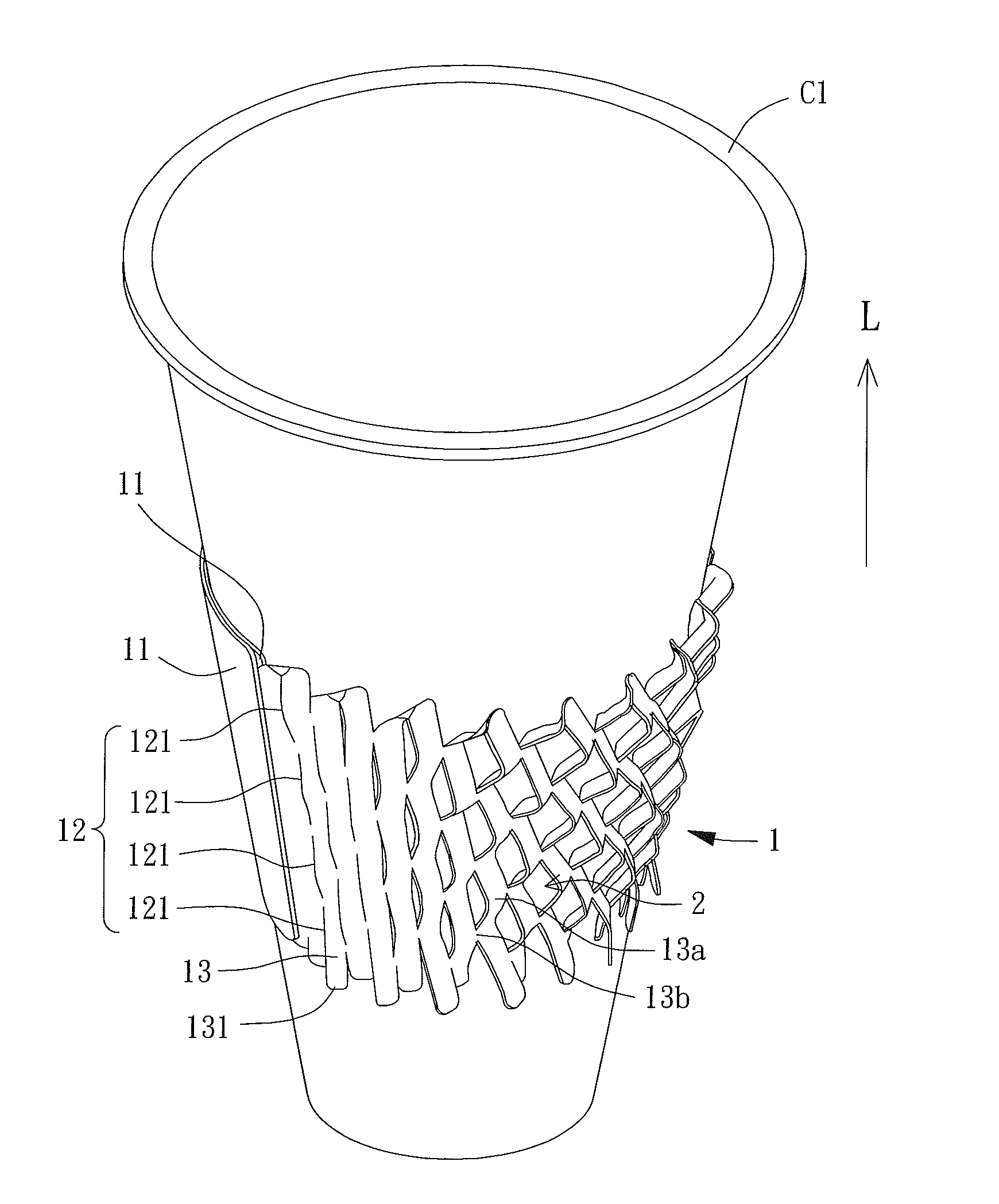
[0059]With reference to FIG. 3a, a thermally insulating member of this disclosure includes a sheet 1. The sheet 1 is generally made of paper, plastic material or other tough material. The sheet 1 includes a first direction X and a second direction Y perpendicular to each other. The sheet 1 has two sides spaced from each other in the first direction X. The two sides of the sheet 1 are able to couple with each other so that the sheet 1 can form a cyclic structure encircling the second direction Y. Namely, the sheet 1 can be folded circular with respect to the second direction Y as an axis and, thus, the sheet 1 is able to form the cyclic structure. The sheet 1 includes a plurality of broken lines 12 extending along the second direction Y. Two adjacent broken lines 12 are spaced from each other in the first direction X. Each broken line 12 includes a plurality of discontinuous slits 121. Namely, two adjacent slits 121 are spaced from each other in the second direction Y. The plurality ...

second embodiment

[0074]Furthermore, with reference to FIGS. 8 and 9, for the plurality of slits 121 of each broken line 12, the slits 121 communicating with one of the peripheries of the sheet 1 in the second direction Y have a first length h1, and the slits 121 communicating with the other periphery of the sheet 1 in the second direction Y have a second length h2. The first length h1 is longer than the second length h2. By such arrangement, when the sheet 1 is mounted around the container C1, a wide opening and a narrow opening are respectively formed at the one and the other periphery since the sheet 1 is stretched outward. The wide opening is larger than the narrow opening and, thus, the cyclic structure formed by the sheet 1 can provide two openings with different sizes. A user can easily mount the sheet 1 around the container C1 via the wide opening, effectively improving the convenience to use the thermally insulating member of this disclosure.

[0075]With reference to FIG. 10, a thermally insul...

third embodiment

[0076]With reference to FIG. 11, in use of the thermally insulating member of the third embodiment, the two sides of the sheet 1 are also able to couple with each other so that the sheet 1 can form a cyclic structure. When the sheet 1 is stretched outward by a container, each of the junctions between the thermally insulating strips 13 and the plurality of slits 121 of the broken lines 12 will deflect away from the container. Meanwhile, since the two second sections 121b of each slit 121 extend towards in the first direction X, each of the second sections 121b can provide a guiding force to bend the adjacent thermally insulating strip 13 and, thus, a fold line 14′ can be formed on the sheet 1. Each fold line 14′ extends towards the two sides of the sheet 1 in the first direction X, so that the fold lines 14′ can help the thermally insulating strips 13 to form the ribs 13a and stretchable ribs 13b. Thus, the heat dissipating holes 2 can be formed between the ribs 13 and stretchable ri...


PUM


Abstract

A thermally insulating member includes a plane sheet having two ends spaced in a length direction and two sides spaced in a thickness direction perpendicular to the length direction. The plane sheet includes a plurality of rows of slits between the ends of the plane sheet. Each row of slits extends from one of the sides through the other side of the plane sheet. A first spacing between two adjacent rows of slits in the length direction is larger than a spacing between two adjacent slits in the same row of slits in a width direction perpendicular to the length and width directions by a second spacing. A thermally insulating strip is defined between two adjacent rows of slits. A stretchable rib is formed between two adjacent slits in the same row of slits. Each end of the plane sheet is a coupling portion free of the slits.

Description

CROSS REFERENCE TO RELATED APPLICATIONS[0001]This is a continuation-in-part application of U.S. patent application Ser. No. 14 / 264,282 filed on Apr. 29, 2014.BACKGROUND OF THE INVENTION[0002]1. Field of the Invention[0003]The present invention relates to a thermally insulating member and, more particularly, to a structure of a thermally insulating member providing an excellent thermally insulating effect such that a container with high temperature is able to be held via the thermally insulating member.[0004]2. Description of the Related Art[0005]With reference to FIGS. 1 and 2, a conventional thermally insulating member 9 includes a sheet. Two ends of the sheet are adapted to couple with each other, so the thermally insulating member 9 can form a cyclic structure. The sheet of the thermally insulating member 9 mainly includes a wavy thermally insulating layer 91 and a surface layer 92. The thermally insulating layer 91 is bonded to the surface layer 92 by an adhesive.[0006]In use of...

Claims


Application Information

Patent Timeline
IPC IPC(8): B65D81/38
CPCB65D81/3876A47G23/0216B65D23/08B65D23/0892B65D81/3865Y10T428/24281Y10T428/24298Y10T428/24306Y10T428/24314Y10T428/24694Y10T428/24777
Inventor ZHANG, SHAO-WEN
Owner BETTER ALLYING DESIGN
Why Eureka
Try Eureka