Suspension device for tilting oxygen converters and converter provided with said suspension device

Inactive Publication Date: 2015-06-04
DANIELI & C OFF MEC SPA
View PDF6 Cites 2 Cited by
  • Summary
  • Abstract
  • Description
  • Claims
  • Application Information

AI Technical Summary

Benefits of technology

[0015]It is a primary scope of the present invention to make a suspension and centering device for a tilting converter container, connecting said container to a supporting ring thereof, which allows both to compensate for thermal expansions, avoidin

Problems solved by technology

Movements are created on the horizontal plane between said two structures of the suspension devices, considering the converter in the vertical position thereof with the mouth facing upwards, because of the thermal expansions of the container and the supporting ring (due to the high temperatures which are generated inside the oven), and consequently of the respective structures connected thereto, said movements causing the creation of clearances or, in the case of compression between the two structures, overload of the parts due to excessive pressure.
If clearance is created between the two structures, the container

Method used


Image

  • Suspension device for tilting oxygen converters and converter provided with said suspension device
  • Suspension device for tilting oxygen converters and converter provided with said suspension device
  • Suspension device for tilting oxygen converters and converter provided with said suspension device

Examples


first embodiment

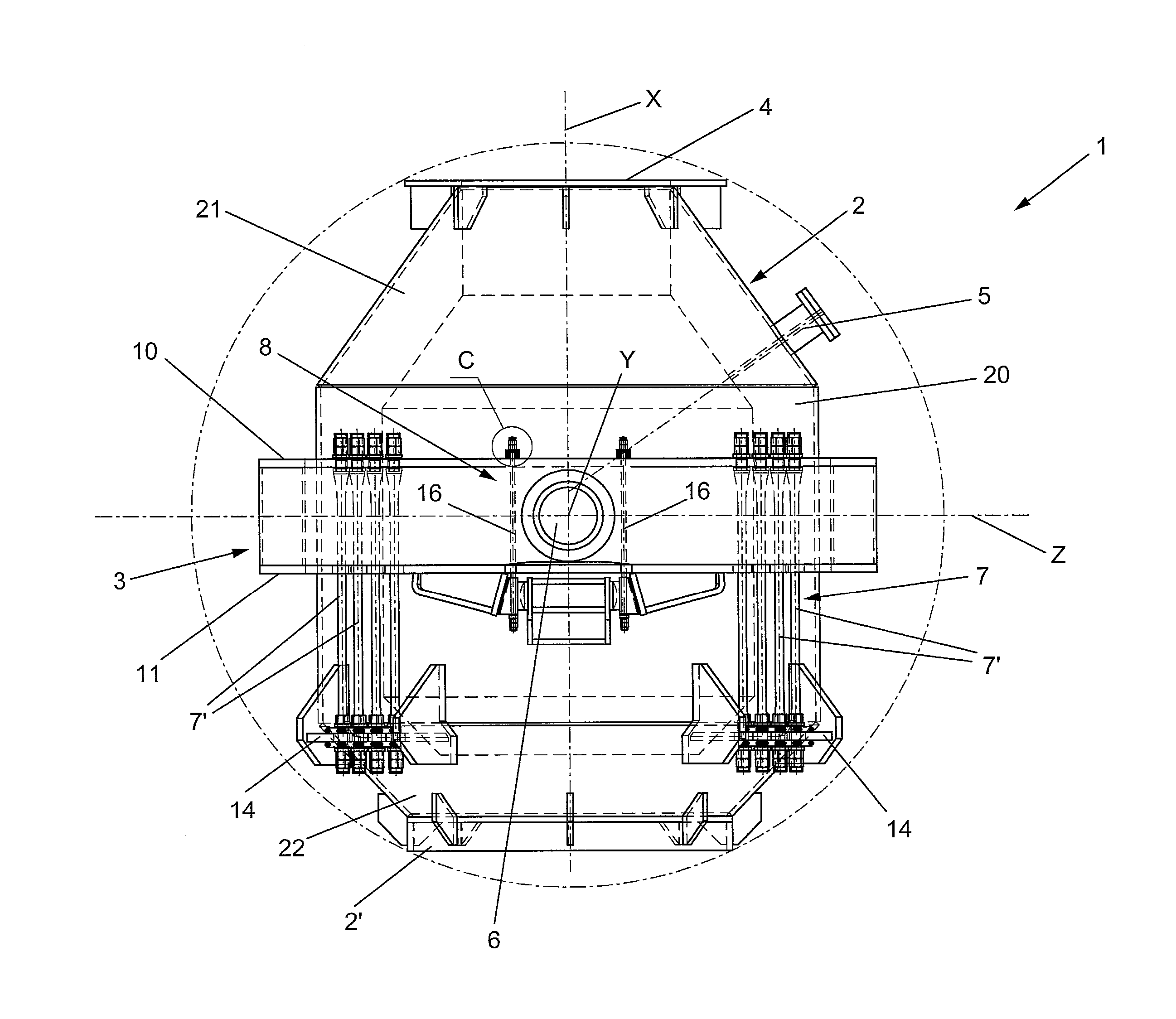
[0068]Figures from 1 to 10 show a tilting converter, indicated by reference numeral 1 as a whole, comprising a suspension device for the horizontal support of the converter, object of the present invention.

[0069]Such a converter 1 comprises:[0070]a container or tank 2, defining an axis X, provided with a loading mouth 4 of the scrap and liquid cast iron and provided with a lateral tapping hole 5 of the liquid steel obtained at the end of the conversion process;[0071]a supporting ring 3 for supporting the container 2, said ring 3 being arranged coaxially to the container 2 and appropriately distanced therefrom;[0072]two supporting pins or tilting pins 6 of said supporting ring 3, known as trunnions, arranged diametrically opposite to each other and defining an axis Y, orthogonal to axis X, with at least one of said supporting pins 6 connected to a tilting mechanism (not shown);[0073]the suspension devices 7, 8 which connect the container 2 to the supporting ring 3 and which also perf...

second embodiment

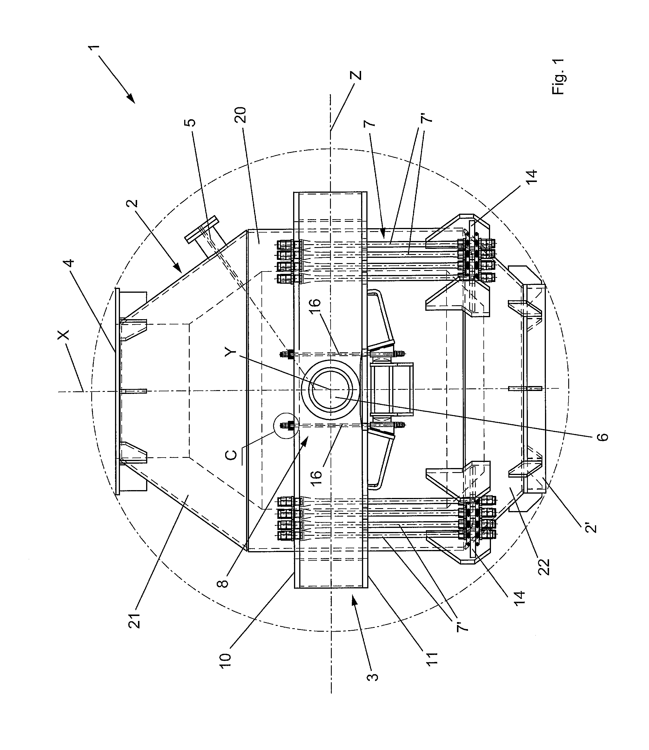
[0097]Figures from 11 to 14 show a tilting converter, indicated by reference numeral 1′ as a whole, comprising a suspension device for the horizontal supporting of the converter object of the present invention.

[0098]Such a converter 1′ comprises all the features of the converter 1, described above, except for the fact that the zone 22′ of the converter 2, containing the bottom of the container, is spherical-bowl-shaped and not conical frustum-shaped. Also in this case, the zone 22′ of the container may alternatively have any appropriate geometry shape.

[0099]Advantageously, the converter 1′ is provided with at least two suspension devices 8 designed for horizontally supporting the converter according to a second variant of the invention.

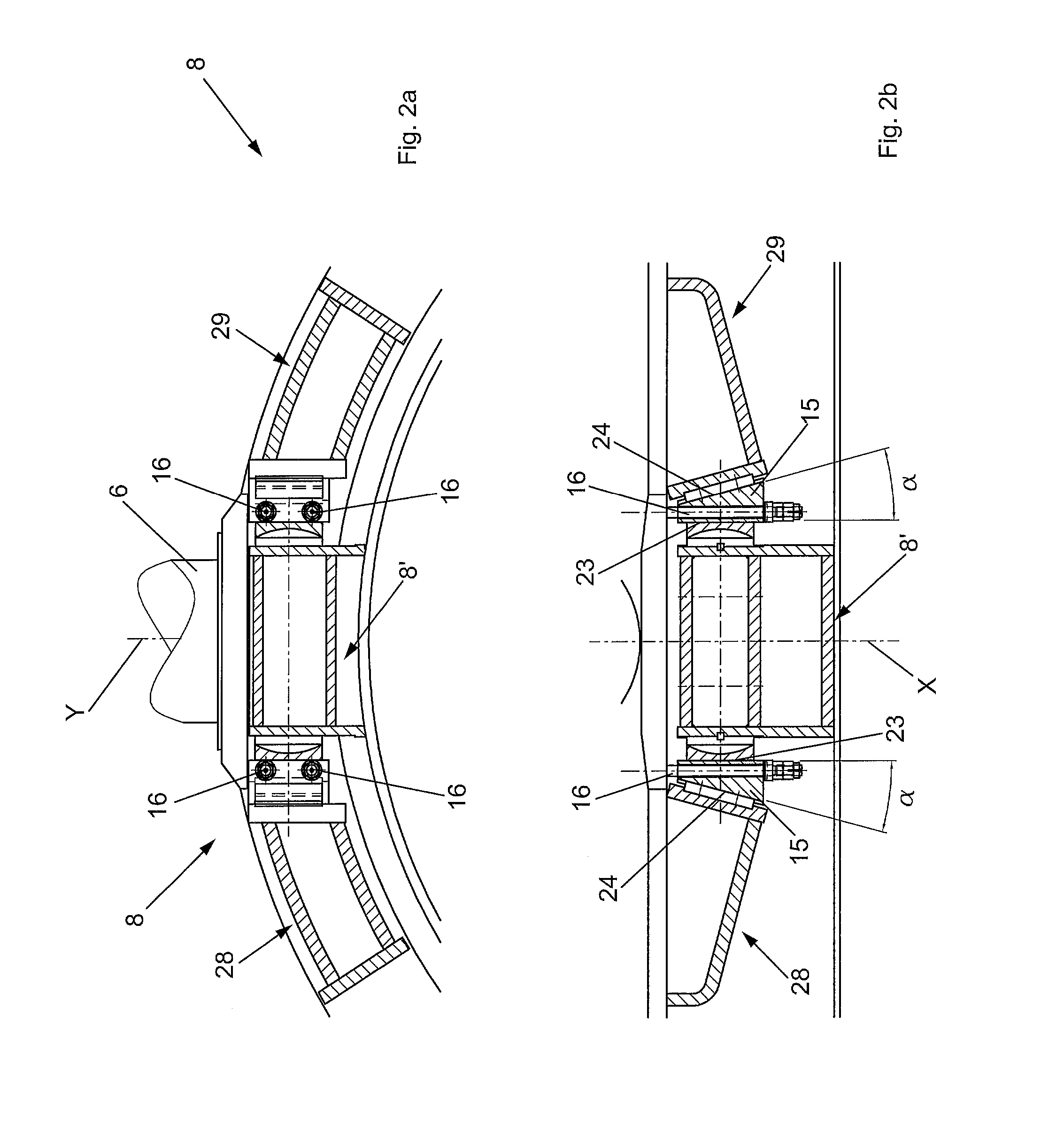
[0100]Such suspension devices 8 comprise:[0101]a central structure 8′ fixed, for example by welding, to the container 2 of the converter 1,[0102]a first side structure 28, arranged at a first side of said central structure 8′, and fixed, for example b...


PUM

PropertyMeasurementUnit
Elasticityaaaaaaaaaa

Abstract

A suspension device (8) for a converter, comprising a central structure (8′), adapted to be fixed to a container (2) of the converter (1), a first lateral structure (29), arranged at a first side of the central structure and adapted to be fixed to a first surface (10, 11) of a supporting ring (3) of the container, a second lateral structure (28), arranged at a second side of said central structure and adapted to be fixed to the surface (10, 11), wherein two wedge-shaped elements (15, 15′) are provided, each element being provided between the central structure and a respective lateral structure and configured so as to slide on sliding surfaces (23, 24, 24′) connected respectively to the central structure and to the respective lateral structure, wherein each wedge-shaped element is crossed by at least one tie-rod (16, 16′) connected thereto, and wherein elastic means (17) are provided, which are associated to or intrinsic with said one tie-rod and configured to maintain a wedging of the wedge-shaped element.

Description

CROSS REFERENCE TO RELATED APPLICATIONS[0001]The present application claims priority to PCT International Application No. PCT / IB2013 / 054132 filed on May 20, 2013, which application claims priority to Italian Patent Application No. M12012A000871 filed May 21, 2012, the entirety of the disclosures of which are expressly incorporated herein by reference.STATEMENT RE: FEDERALLY SPONSORED RESEARCH / DEVELOPMENT[0002]Not Applicable.FIELD OF THE INVENTION[0003]The present invention relates to a suspension device for tilting oxygen converter containers and to a converter provided with at least one pair of such suspension devices connecting the container to a supporting ring.STATE OF THE ART[0004]The main object of an oxygen converter is to convert the cast iron produced in the blast furnace into raw liquid steel, which may be subsequently refined in the secondary steel production department.[0005]The main functions of the oxygen converter, also known as B.O.F. (Basic Oxygen Furnace), are to d...

Claims


Application Information

Patent Timeline
IPC IPC(8): C21C5/50F27B3/06
CPCF27B3/065C21C5/50C21C5/4633
Inventor POLONI, ALFREDONOBILE, MATTEO
Owner DANIELI & C OFF MEC SPA
Why Eureka
Try Eureka