Electrically connecting structure, glass plate with terminal having the same, and method of manufacturing glass plate with terminal

a technology of glass plate and terminal, which is applied in the direction of final product manufacturing, coupling device connection, sustainable manufacturing/processing, etc., can solve the problems of not much progress in the use of such solder, the difficulty of obtaining the sufficient adhesion required by the vehicle window glass using the conductive adhesive, and the cost of lead replacement in such solder, etc., to achieve sufficient adhesion and conductivity

Active Publication Date: 2015-06-04
ASAHI GLASS CO LTD
View PDF7 Cites 14 Cited by
  • Summary
  • Abstract
  • Description
  • Claims
  • Application Information

AI Technical Summary

Problems solved by technology

However, replacements for the lead in such solder, such as indium, tin, silver, or the like, are expensive, and not much advances have been made regarding the use of such solder.
However, it is difficult to obtain a sufficient adhesion required by the vehicle window glass using the conductive adhesive.
Even if a resin content of the conductive adhesive is increased in order to increase the adhesion, the conductivity decreases (resistance increases), and thus, it is difficult to simultaneously obtain sufficient adhesion and conductivity.

Method used


Image

  • Electrically connecting structure, glass plate with terminal having the same, and method of manufacturing glass plate with terminal
  • Electrically connecting structure, glass plate with terminal having the same, and method of manufacturing glass plate with terminal
  • Electrically connecting structure, glass plate with terminal having the same, and method of manufacturing glass plate with terminal

Examples


Embodiment Construction

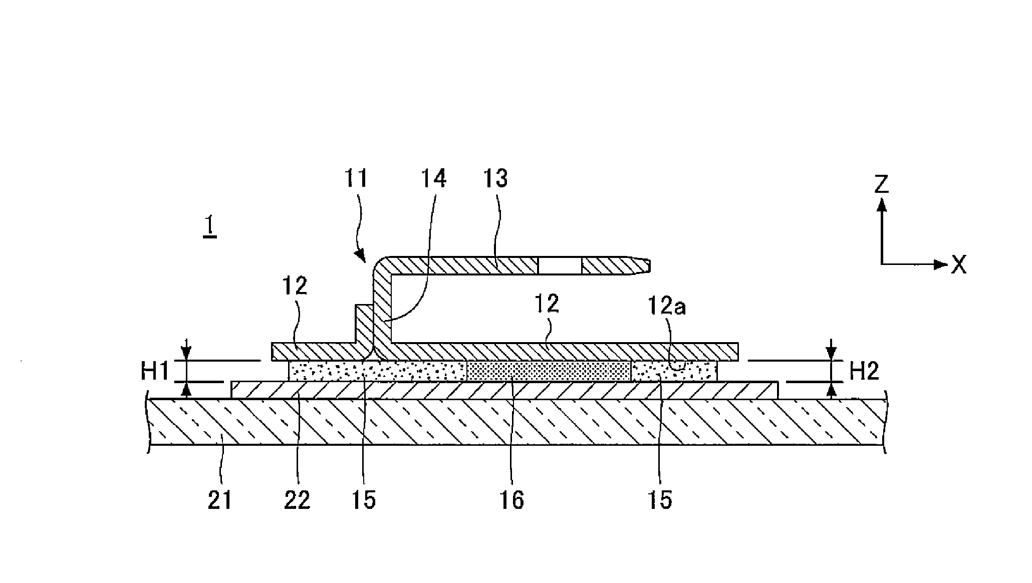
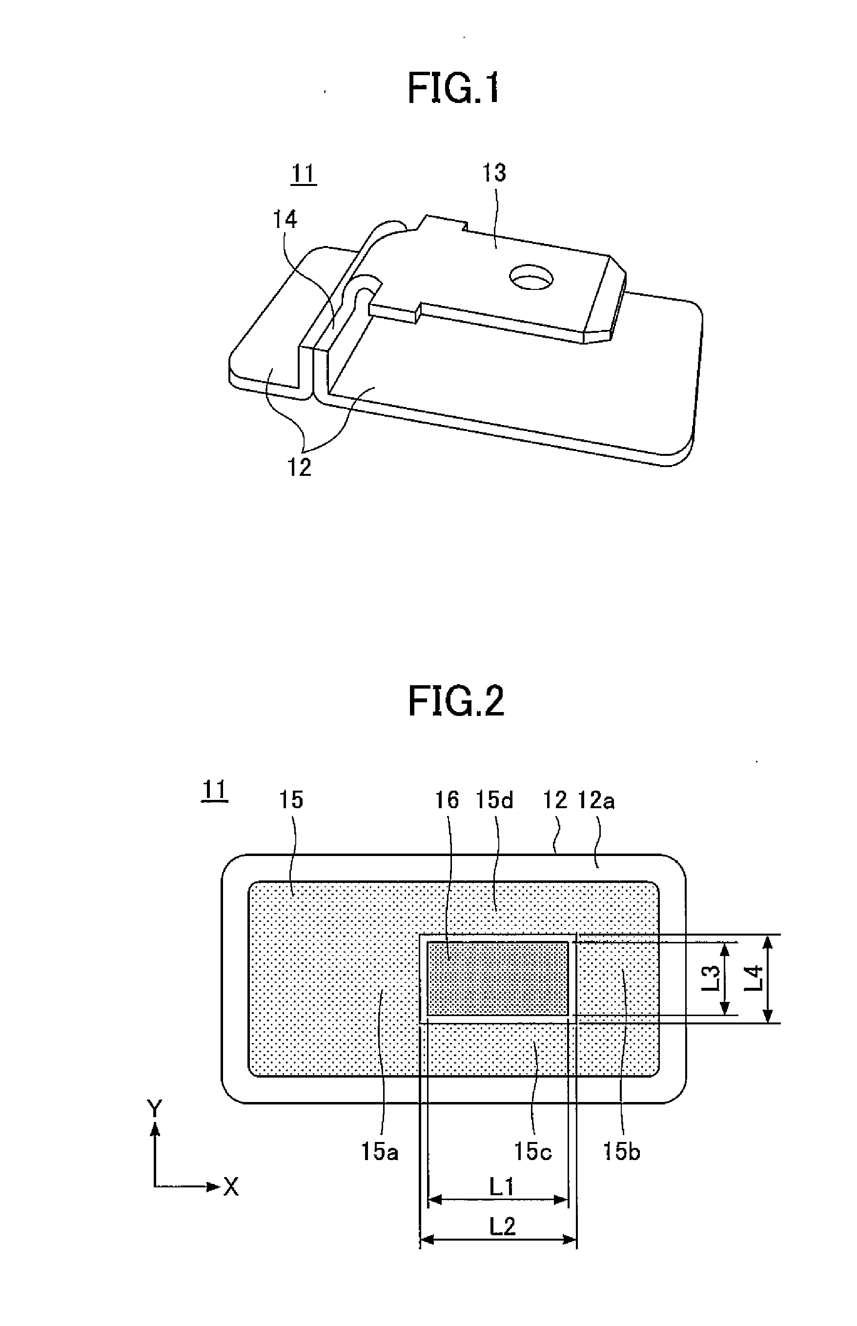
[0028]FIG. 1 is a perspective view of a terminal 11 used in one embodiment of the present invention. The terminal 11 is a cable terminal for a vehicle, to which a cable that is not illustrated, such as a wire harness of the vehicle, is connected. The terminal 11 is formed by a thin plate made of a conductive metal such as copper or the like, and is preferably tin-plated. The terminal 11 includes a base part 12, a male terminal part 13, and a support part 14.

[0029]The base part 12 is a metal member that has an elongated rectangular plate shape for mounting the terminal 11 on a glass plate that is not illustrated. The male terminal part 13 is a flat tab terminal to which the cable is to be connected, and is formed according to Japan Industrial Standards JIS D5403 PA (or may be PB), for example. The support part 14 is a member that projects from the base part 12, and supports a base of the male terminal part 13 in order to secure a predetermined distance between the base part 12 and th...


PUM


Abstract

An electrically connecting structure includes a glass plate, a feeding part formed on the glass plate, a terminal having a base part opposing the glass plate, an adhesive adhering the glass plate and the terminal, and a conductive rubber arranged between the feeding part and the base part. The adhesive is a thermosetting adhesive that once softens when heated and thereafter cures, and is arranged to surround a periphery of the conductive rubber. The feeding part and the base part have electrical continuity via the conductive rubber.

Description

CROSS-REFERENCE TO RELATED APPLICATIONS[0001]This application is a continuation application filed under 35 U.S.C. 111(a) claiming the benefit under 35 U.S.C. 120 and 365(c) of PCT International Application No. PCT / JP2013 / 071530 filed on Aug. 8, 2013, which is based upon and claims the benefit of priority of Japanese Patent Application No. 2012-178993 filed on Aug. 10, 2012, the entire contents of which are incorporated herein by reference.BACKGROUND OF THE INVENTION[0002]1. Field of the Invention[0003]The present invention relates to an electrically connecting structure for a glass plate and a terminal, a glass plate with terminal having the same, and a method of manufacturing the glass plate with terminal.[0004]2. Description of the Related Art[0005]In a vehicle window glass, solder that includes lead is used to bond a terminal and a conductor formed on a surface of a glass plate. Recently, the use of solder that includes no lead is desired in order to reduce environmental load or ...

Claims


Application Information

Patent Timeline
Patent Type & Authority Applications(United States)
IPC IPC(8): H01R13/24H01R4/04
CPCH01R4/04H01R13/2414H01R13/04H01R43/00H01R2201/26H01R43/007H01R12/57B32B17/10293B32B17/10853H01R4/70H01R2101/00H05K3/325H05K3/305H05K2201/09909H05K2201/0314H05K2201/1031Y02P70/50
Inventor TAKEUCHI, SHOICHITERASHIMA, FUMITAKATORIUMI, NAOHITOSAITA, EIJI
Owner ASAHI GLASS CO LTD
Why Eureka
Try Eureka