
System for following an object marked by a tag device with a camera

a technology of tag device and camera, which is applied in the field of cameras, can solve the problems of limited precision of camera control and limited supply of positional information

Inactive Publication Date: 2015-06-04
AXIS
View PDF4 Cites 35 Cited by
  • Summary
  • Abstract
  • Description
  • Claims
  • Application Information

AI Technical Summary

Benefits of technology

The present invention provides an improved system for following an object marked by a tag device with a camera. The system measures the horizontal plane position and altitude of both the tag device and the camera using different principles, such as air pressure and acceleration. This enables better control of the camera's pan and tilt settings, even in situations where external disturbances influence the measurements. By canceling out the effects of external disturbances, the system becomes more precise and reliable. Additionally, the system can adjust the camera settings based on the difference in horizontal plane positions between the tag device and the camera, making it easier to focus on the right distance. This improves the stability and speed of object tracking. The accelerometer data can be used to update the horizontal plane position and altitude of the tag device, further improving the control of the camera's pan and tilt setting. Overall, the system provides a better and more accurate method for following tagged objects with a camera.

Problems solved by technology

A drawback of global positioning techniques is that they provide positional information having a limited precision, in particular when it comes to measuring altitude.
Thus, if the control of the camera is based on global positioning techniques the control of the camera will have a limited precision, in particular in the tilt direction.

Method used


Image

  • System for following an object marked by a tag device with a camera
  • System for following an object marked by a tag device with a camera
  • System for following an object marked by a tag device with a camera

Examples


Embodiment Construction

[0033]The present invention will now be described more fully hereinafter with reference to the accompanying drawings, in which currently preferred embodiments of the invention are shown. This invention may, however, be embodied in many different forms and should not be construed as limited to the embodiments set forth herein; rather, these embodiments are provided for thoroughness and completeness, and fully convey the scope of the invention to the skilled person. The systems and devices disclosed herein will be described during operation.

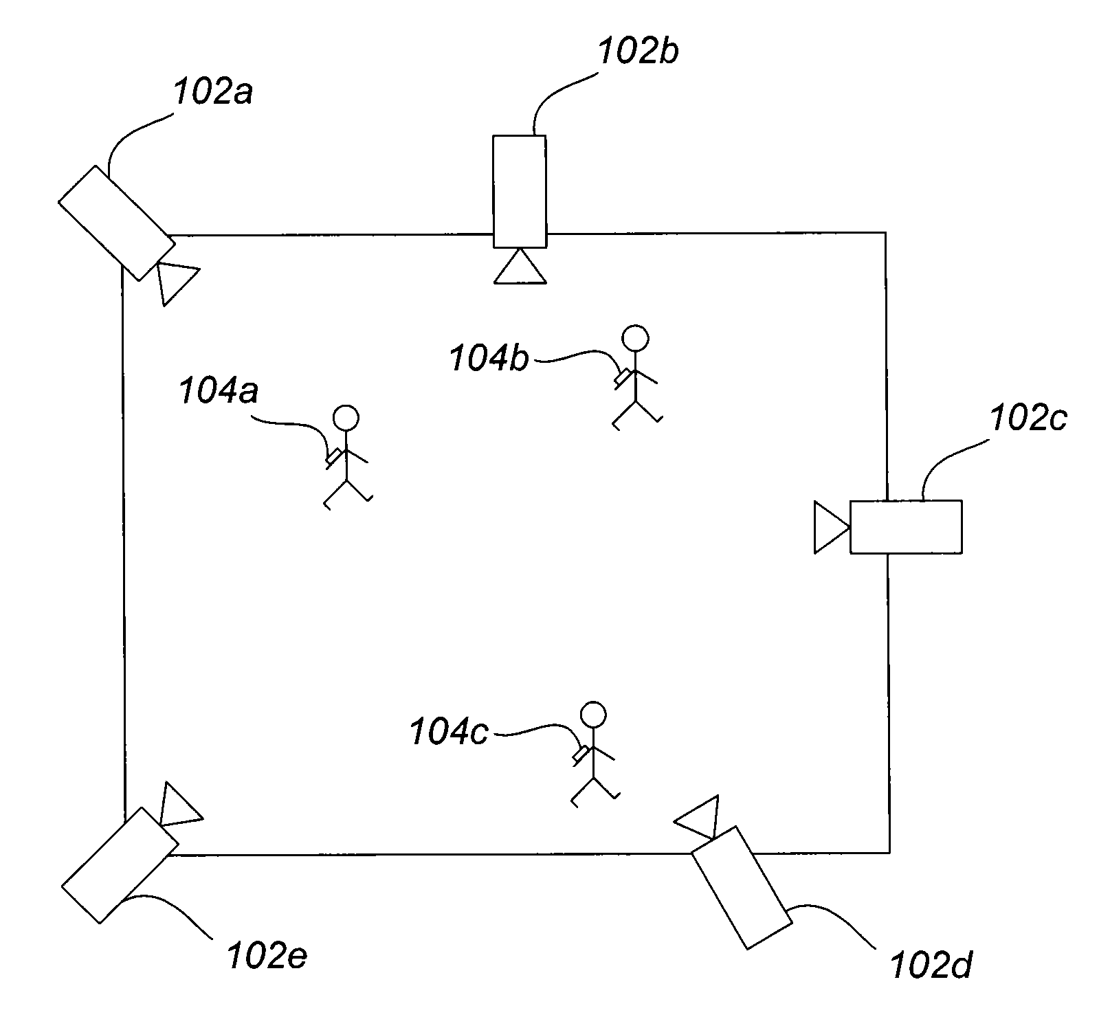
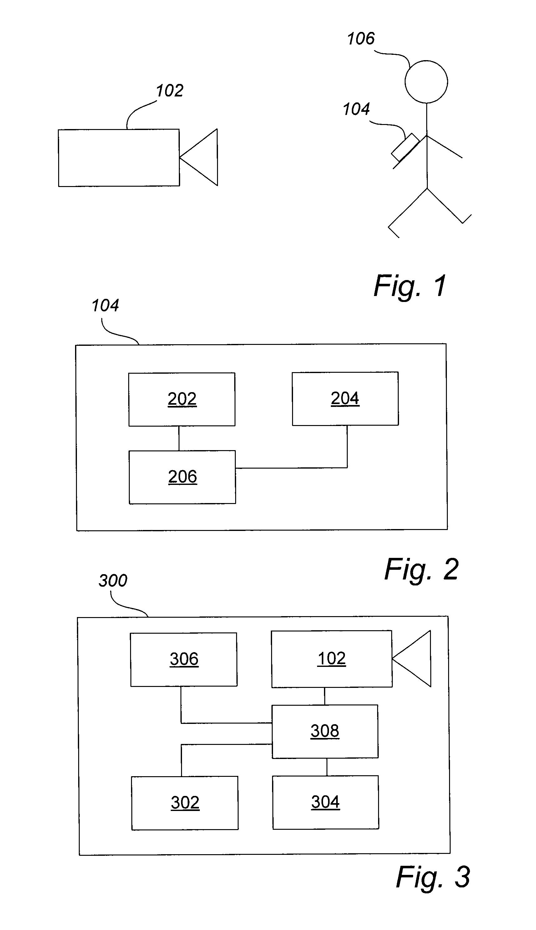
[0034]FIG. 1 illustrates a camera 102 and an object 106 to be followed by the camera 102. The object 106 may e.g. be a person, such as a security staff member, or any other object 106 that moves relative to the camera 102. The camera 102 is typically a pan-tilt-zoom camera whose settings may be controlled to keep the object 106 in the field of view of the camera 102. In order to facilitate the tracking of the object 106 and thereby facilitate the c...


PUM


Abstract

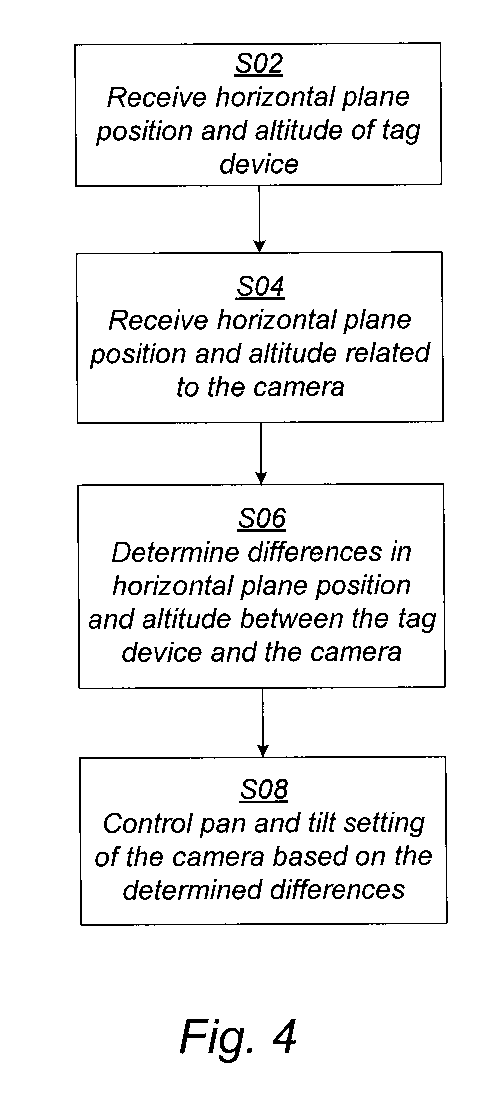
There is provided a system, including a tag device and a camera arrangement, for following an object marked by the tag device with a camera. The tag device may measure a horizontal plane position and an altitude of the tag device according to different measurement principles, and transmit the measured values to a camera arrangement. The camera arrangement may measure a horizontal plane position and an altitude related to the camera according to different measurement principles. The camera arrangement may then control the pan and tilt settings of the camera based on differences in horizontal plane positions and altitudes between the camera and the tag device such that the camera is oriented in the direction of the tag device.

Description

TECHNICAL FIELD[0001]The present invention relates to the field of cameras and in particular to a system for following an object marked by a tag device with a camera.BACKGROUND[0002]There are situations in which it is important to automatically follow a moving object, such as a person, by means of a camera. An example of such a situation is to follow security staff with a pan-tilt-zoom (PTZ) camera in order to increase their safety. In order to facilitate tracking of a moving object, it may be marked by a tag device which communicates with the camera. For example, a person to be tracked may wear or carry with it a tag device which transmits positional information to the camera.[0003]WO 2013 / 131036 A1 discloses a system for pointing a camera at a remote target. The pointing of the camera is controlled by a combination of location information obtained by global positioning technology and orientation information obtained by line of sight detection. In particular, for short distances (t...

Claims


Application Information

Patent Timeline
IPC IPC(8): H04N5/232
CPCH04N5/23203H04N5/23296H04N23/695G06K19/07H04N7/18H04N23/69H04N23/66
Inventor LUNDBERG, STEFAN
Owner AXIS
Learn More