
Optically controlled lighting device and control method thereof

a technology of lighting device and control method, which is applied in the field of lighting technology, can solve the problems of troublesome user's frequent turning on or turning off the switch of the light source, waste of electric power, and the operation method of this power-saving lamp still has some drawbacks, so as to reduce increase or maintain the brightness of the lighting main body, and save electric power

Inactive Publication Date: 2015-06-04
LIVINGSTYLE ENTERPRISES
View PDF6 Cites 5 Cited by
  • Summary
  • Abstract
  • Description
  • Claims
  • Application Information

AI Technical Summary

Benefits of technology

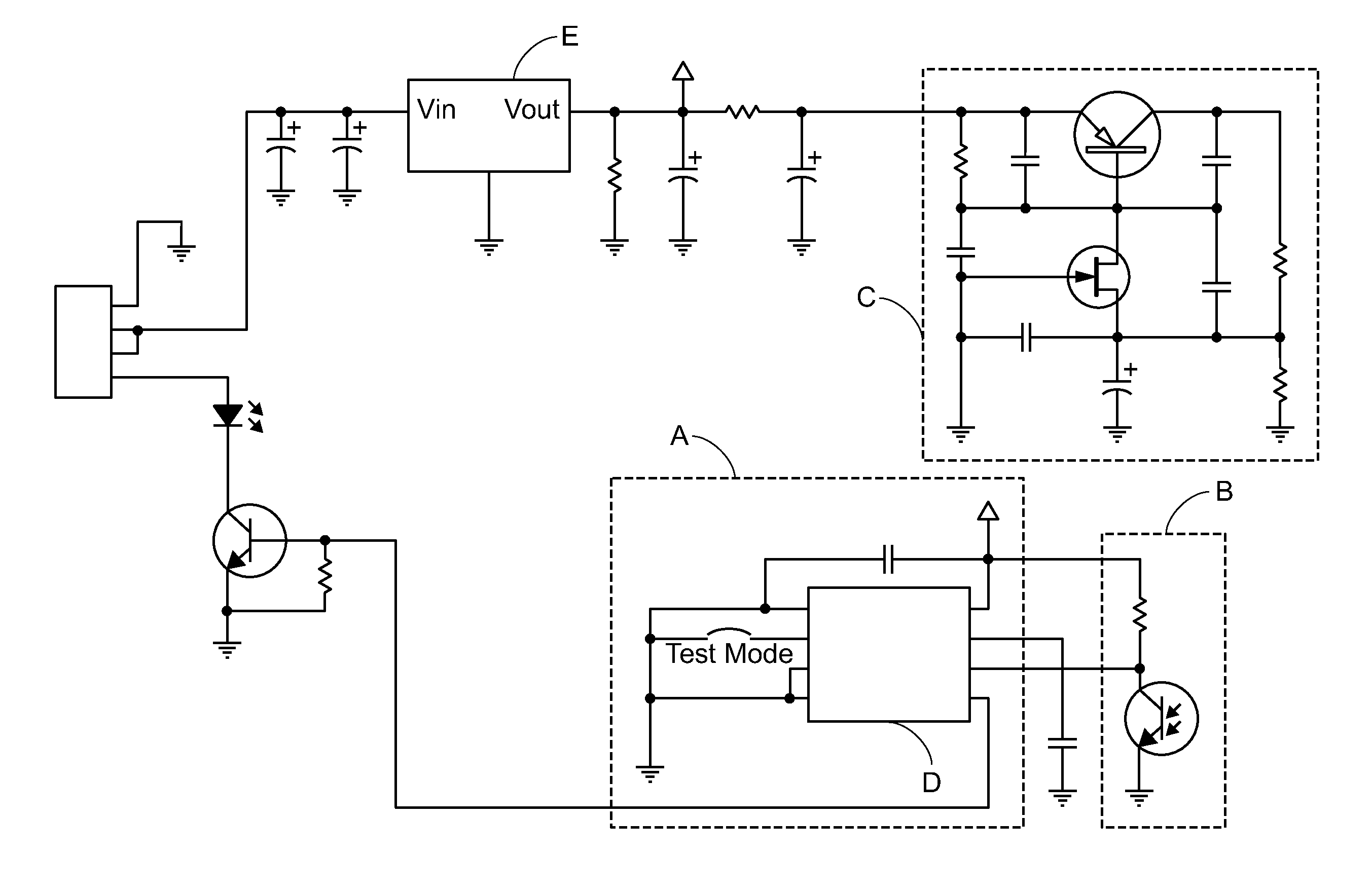
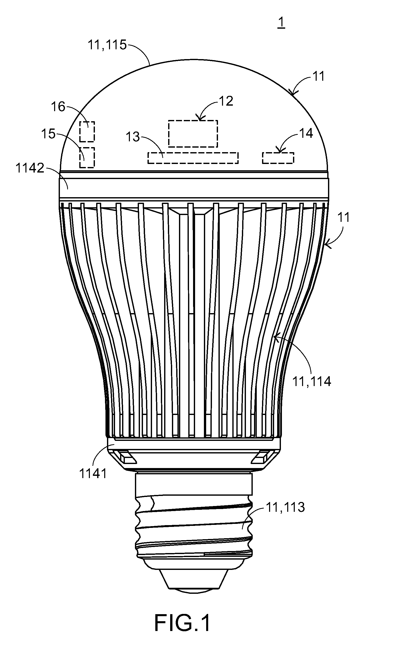
The present invention provides an optically controlled lighting device with an optical detector and control method to save power and balance brightness in a lighting zone. The device detects the brightness of the ambient light and adjusts the brightness of the lighting main body accordingly to achieve energy savings and optimal lighting. This design eliminates flickering, and the user doesn't need to constantly turn on and off the light source. The switch is always on, resulting in continuous energy savings.

Problems solved by technology

The way of additionally implementing the lighting action of the lighting device wastes electric power.
If the switch of the light source is far away from the user or the user is handicapped, the process of frequently turning on or turning off the switch of the light source is troublesome to the user.
However, the operating method of this power-saving lamp still has some drawbacks.
As mentioned above, it is inconvenient to install the power-saving lamp, and the installation cost of the power-saving lamp is high.
Moreover, the demands on the installation site of the power-saving lamp are stringent.

Method used


Image

  • Optically controlled lighting device and control method thereof
  • Optically controlled lighting device and control method thereof
  • Optically controlled lighting device and control method thereof

Examples


first embodiment

[0110]FIG. 16 schematically illustrates a group control mechanism of an optically controlled lighting group including plural optically controlled lighting devices according to the present invention. As shown in FIG. 16, five optically controlled lighting devices 81˜85 are located within a detection space 8. The optically controlled lighting device 81 is a sensing type lighting device with a dimming time controller, an optical detector, a sensing element and an electromagnetic wireless communication module. In addition, the optically controlled lighting device 81 at least has a master control function.

[0111]Each of the optically controlled lighting devices 82˜85 is a non-sensing type lighting device (e.g. an ordinary lighting device) with an electromagnetic wireless communication module. In addition, each of the optically controlled lighting devices 82˜85 only has a controlled function. That is, each of the optically controlled lighting devices 82˜85 can only be passively controlled ...

second embodiment

[0115]FIG. 17 schematically illustrates a group control mechanism of an optically controlled lighting group including plural optically controlled lighting devices according to the present invention. As shown in FIG. 17, five optically controlled lighting devices 91˜95 are located within a detection space 9. Each of the optically controlled lighting devices 91˜95 is a sensing type optically controlled lighting device with a dimming time controller, an optical detector, a sensing element and an electromagnetic wireless communication module. In addition, each of the optically controlled lighting devices 91˜95 has both of a master control function and a controlled function.

[0116]According to the results of sensing the light intensity changes of sub-regions of respective optically controlled lighting devices 91˜95, the optically controlled lighting devices 91˜95 issues or transmits back a lighting control command C2 to other optically controlled lighting devices in an electromagnetic wir...

third embodiment

[0118]The present invention also relates to another group control mechanism of an optically controlled lighting group in different spaces or different regions. This group control mechanism may be implemented by installing additional electromagnetic wireless communication modules in the optically controlled lighting devices. FIG. 18 schematically illustrates a group control mechanism according to the present invention by integrating the concepts of the group control mechanism of FIG. 16 with the group control mechanism of FIG. 17. In this embodiment, the optically controlled lighting device 81 may be in communication with and in coordination with the optically controlled lighting devices 91˜95 through a lighting control command C3 and another lighting control program.

[0119]From the above descriptions, the optically controlled lighting device of the present invention is equipped with a dimming time controller to control the on state and the off state of the lighting main body. Moreove...


PUM


Abstract

An optically controlled lighting device and a control method thereof are provided. The optically controlled lighting device includes a lighting main body, a dimming time controller and an optical detector. The control method includes the following steps. In a step (a), the lighting main body, including a controlling circuit and a light source, the dimming time controller and the optical detector are provided. In a step (b), the dimming time controller is enabled to respectively generate an on / off dimming signal, and the light source is respectively turned on / turned off during an on / off period respectively corresponding to the on / off dimming signal, wherein the off period is shorter than the time period for producing persistence of vision. In a step (c), an ambient light intensity is detected by the optical detector during the off period, the brightness of the light source is increased or decreased or the light source is turned off.

Description

FIELD OF THE INVENTION[0001]The present invention relates to a lighting technology, and more particularly to an optically controlled lighting device for detecting the ambient light intensity and a control method thereof.BACKGROUND OF THE INVENTION[0002]Nowadays, lighting devices are widely used in workshops, working platforms, walkways, offices, houses, roads, courtyards, public places or a variety of indoor / outdoor environments, and bring a lot of convenience to the human lives. For example, the wisely-used lighting devices at least comprise light bulbs, light tubes, various lamps (e.g. a ceiling lamp or a garden lamp) or various work lamps (e.g. a work lamp with a humidifying function or a work lamp with a spraying function). The light sources used in these lighting devices are for example incandescent light bulbs, fluorescent lamps or environmentally-friendly and power-saving LED lamps.[0003]Conventionally, for achieving the power-saving efficacy of the lighting device, a passive...

Claims


Application Information

Patent Timeline
Patent Type & Authority Applications(United States)
IPC IPC(8): H05B37/02F21V29/70H05B33/08H05B44/00
CPCH05B37/0218F21V29/70H05B33/0854H05B37/0272F21V23/0464F21V29/83F21K9/232F21K9/27H05B47/11Y02B20/30Y02B20/40H05B47/115H05B47/19H05B47/155H05B45/12
Inventor CHEN, MING-YUN
Owner LIVINGSTYLE ENTERPRISES
Learn More