Image forming apparatus, calibration method, and drying determination method

a technology of image forming apparatus and drying determination method, which is applied in the direction of optical radiation measurement, instruments, spectrometry/spectrophotometry/monochromators, etc., can solve the problems of generating unnecessary drying standby time and difficulty in correctly setting drying standby tim

Active Publication Date: 2015-06-11
RICOH KK
View PDF4 Cites 35 Cited by
  • Summary
  • Abstract
  • Description
  • Claims
  • Application Information

AI Technical Summary

Benefits of technology

[0007]It is an object of the present invention to at least

Problems solved by technology

Due to this, in the technique disclosed in Japanese Patent Application Laid-open No. 2010-241061, it is

Method used


Image

  • Image forming apparatus, calibration method, and drying determination method
  • Image forming apparatus, calibration method, and drying determination method
  • Image forming apparatus, calibration method, and drying determination method

Examples


first modification

[0174

[0175]Next, a modification of the processing performed by the colorimetry starting control unit 150 implemented as a function of the CPU 101 will be described.

[0176]FIG. 22 is a diagram illustrating an example of a test pattern used in the first modification. As illustrated in FIG. 22, the test pattern used in the first modification includes a plurality of patch rows (eight rows in FIG. 22) arranged along a sub-scanning direction B, each of which includes a predetermined number of the patches 200 (seven patches 200 in FIG. 22) arranged along the main-scanning direction A. In the test pattern, the patches 200 for which drying time is relatively long are arranged in patch rows that are printed earlier in the order of printing, and the patches 200 for which drying time is relatively short are arranged in patch rows that are printed later in the order of printing. In a single patch row in which the order of printing is the same, the patch 200 for which the drying time is longest is...

second modification

[0198

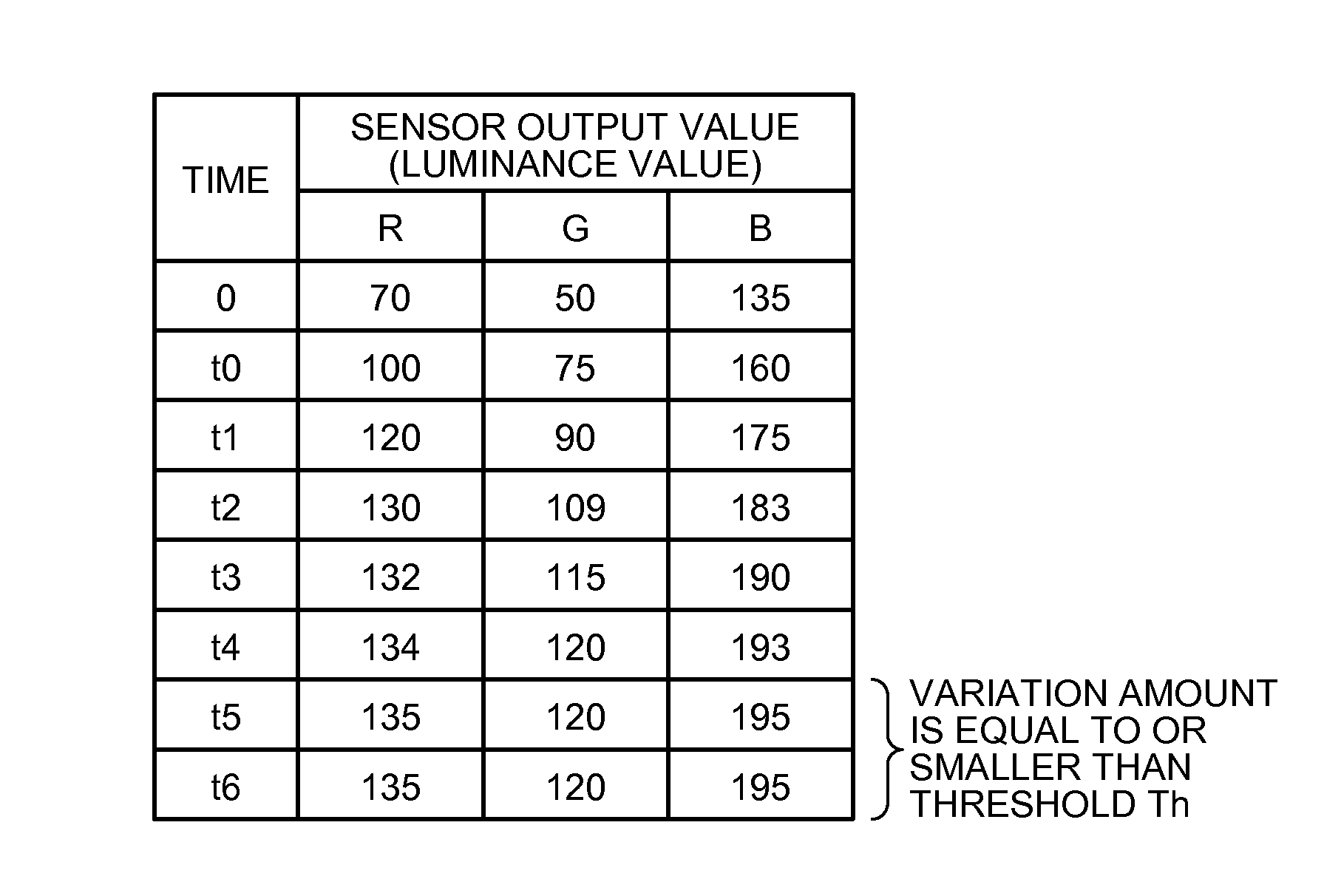
[0199]In the embodiment and the first modification as described above, the RGB value of the representative patch Prep included in the test pattern printed on the printing medium P is measured at different points of time by using the colorimetric camera 20, and drying of the patch 200 included in the test pattern is determined based on whether the variation amount is equal to or smaller than the threshold Th. However, the drying determination method as described above may be effectively applied to a method of determining drying of an arbitrary image (hereinafter, referred to as an actual image), not limited to the test pattern including the patch 200, printed on the printing medium P.

[0200]For example, when ink is ejected to the printing medium P made of vinyl chloride or the like, it takes time until the ink on the printing medium P (that is, an image formed with the ink) is dried. Therefore, conventionally, a long drying standby time is set, and next processing, such as convey...

third modification

[0210

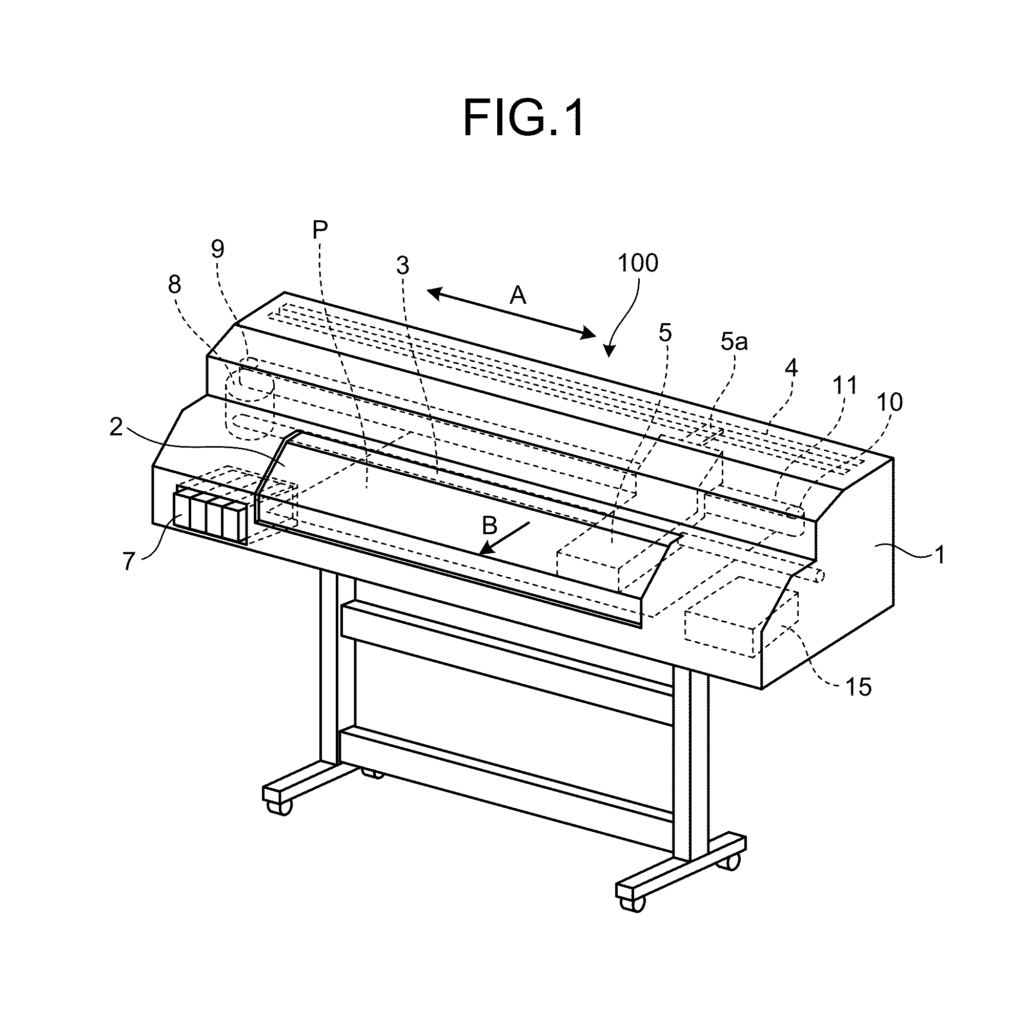
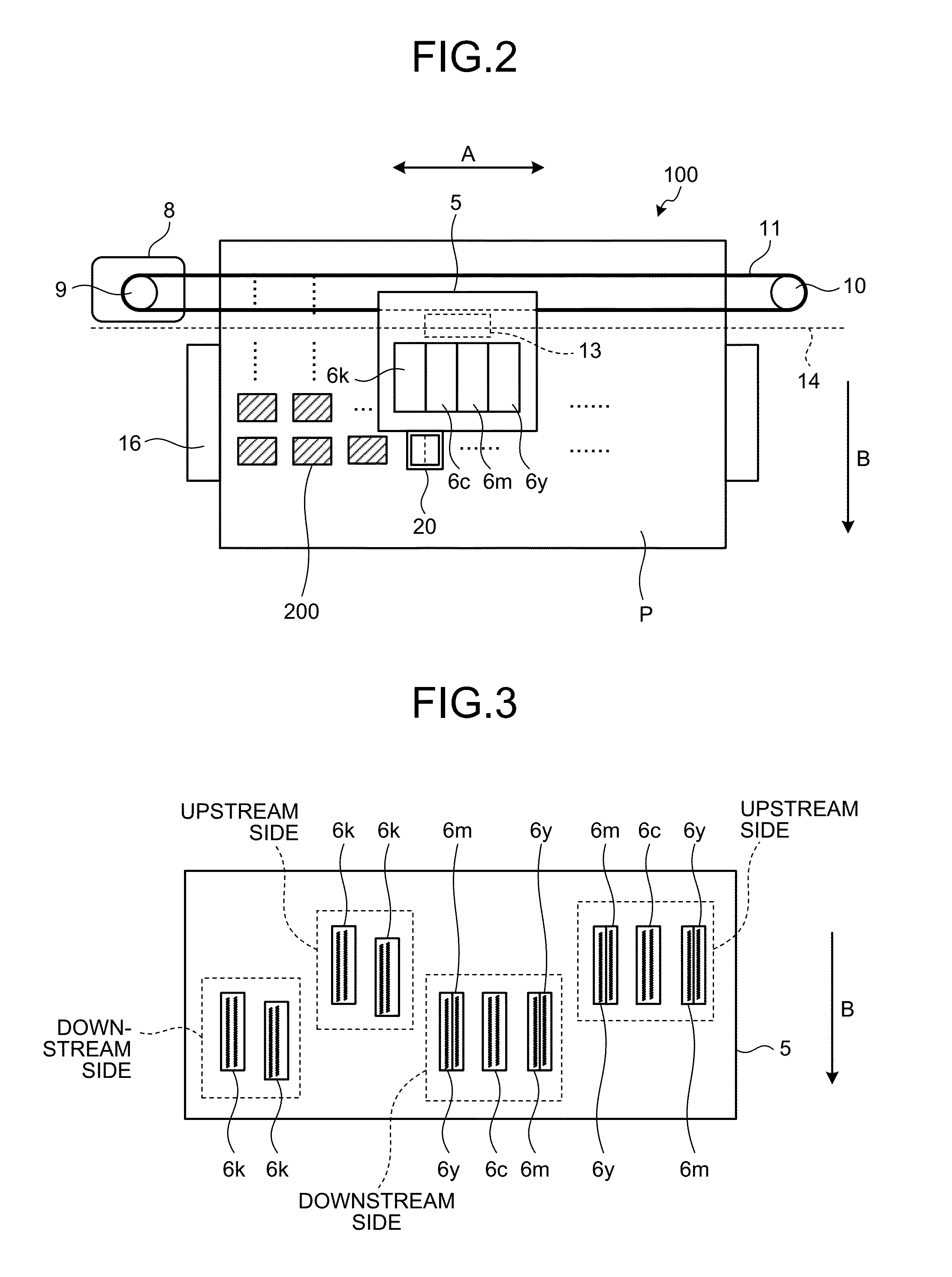
[0211]In the embodiment and modifications described above, a serial-head ink-jet printer is exemplified as an example of the image forming apparatus 100. However, the present invention is not limited to the example described above, and can be effectively applied to various types of image forming apparatuses that form images by ejecting ink to the printing medium P. For example, when the present invention is applied to a line-head ink-jet printer, a plurality of the colorimetric cameras 20 may be arranged in a direction perpendicular to the conveying direction of the printing medium P.

[0212]According to the embodiments described above, colorimetry of a colorimetric object can be started at an appropriate timing irrespective of print conditions for a colorimetric object.


PUM


Abstract

An image forming apparatus includes a printing unit that prints at least one object image using a color material; a color information acquiring unit that acquires color information of the object image; and a control unit that starts one of colorimetry of the object image using the color information acquired by the color information acquiring unit and color adjustment of the printing unit after a variation amount of color information of the object image measured at different points of time is equal to or smaller than a predetermined threshold.

Description

CROSS-REFERENCE TO RELATED APPLICATIONS[0001]The present application claims priority to and incorporates by reference the entire contents of Japanese Patent Application No. 2013-254553 filed in Japan on Dec. 9, 2013 and Japanese Patent Application No. 2014-243562 filed in Japan on Dec. 1, 2014.BACKGROUND OF THE INVENTION[0002]1. Field of the Invention[0003]The present invention relates to an image forming apparatus, a calibration method, and a drying determination method.[0004]2. Description of the Related Art[0005]In the related art, as a calibration method in an image forming apparatus, known is a technique of performing colorimetry, with a colorimeter, on a pattern printed by the image forming apparatus using a color material, and updating a correction value for performing gradation correction of density based on an obtained colorimetric value (for example, refer to Japanese Patent Application Laid-open No. 2010-241061). The color of the pattern printed by the image forming appar...

Claims


Application Information

Patent Timeline
IPC IPC(8): B41J2/21G01N21/25
CPCB41J2/2107B41J2/2132G01N21/251H04N1/6033G01J3/0205G01J3/462G01J3/524
Inventor FUJII, MASAYUKISATOH, NOBUYUKIYORIMOTO, MAMORUKOBAYASHI, MASATOMATSUMOTO, HIROSHIHORIKAWA, DAISAKUYOKOZAWA, SUGURUMORITA, KENJISAKURADA, YUICHISASA, TOMOHIROKAWARADA, MASAYA
Owner RICOH KK
Why Eureka
Try Eureka