Air Flap Device
- Summary
- Abstract
- Description
- Claims
- Application Information
AI Technical Summary
Benefits of technology
Problems solved by technology
Method used
Image

Examples
Embodiment Construction
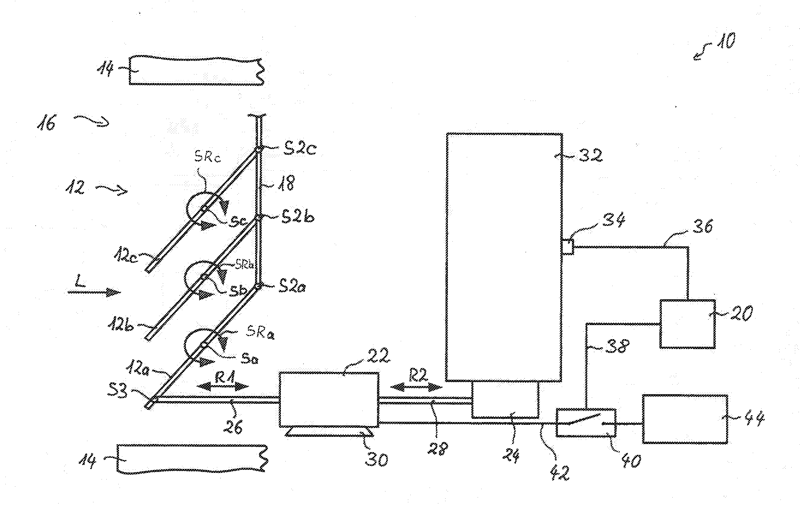
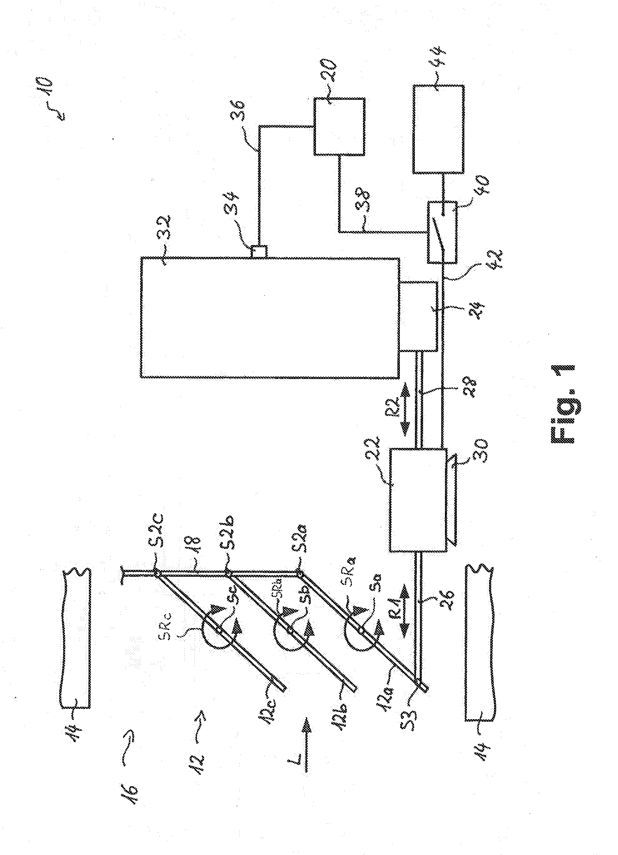
[0029]FIG. 1 shows an air flap device designated more generally with 10, which, for example, can be installed in a motor vehicle. It comprises an air flap 12, which can comprise a plurality of lamella-like air flaps 12a, 12b, 12c, which are accommodated swivelable on a housing 14 around respective pivot axes Sa, Sb, Sc in respective swivel directions SRa, SRb, SRc such that by swiveling the air flaps 12a, 12b, 12c, the effective flow cross-section of a flow passage opening 16 defined in the housing 14 can be changed.
[0030]Although only three air flaps 12a, 12b, 12c are provided in this embodiment, their number, however, is not limited to three, but one of three different numbers of air flaps can also be provided, for example, only a single air flap. The air flaps 12a, 12b, 12 can each have an area that is smaller than the flow passage opening 16. In that way, in contrast to the case where only a single air flap is provided, whose area essentially corresponds to that of the flow pass...
PUM
 Abstract
Description
Claims
Application Information