Packing structure

Active Publication Date: 2015-06-11
PANASONIC ECOLOGY SYSTEMS GUANGDONG CO LTD +1
View PDF18 Cites 0 Cited by
  • Summary
  • Abstract
  • Description
  • Claims
  • Application Information

AI Technical Summary

Benefits of technology

[0023]The packing structure according to the embodiments of the present invention is advantage

Problems solved by technology

Since a large number of cartons need to be transported, man hours are increased; both the large cartons and the small carton are used, th

Method used


Image

  • Packing structure
  • Packing structure
  • Packing structure

Examples


first embodiment

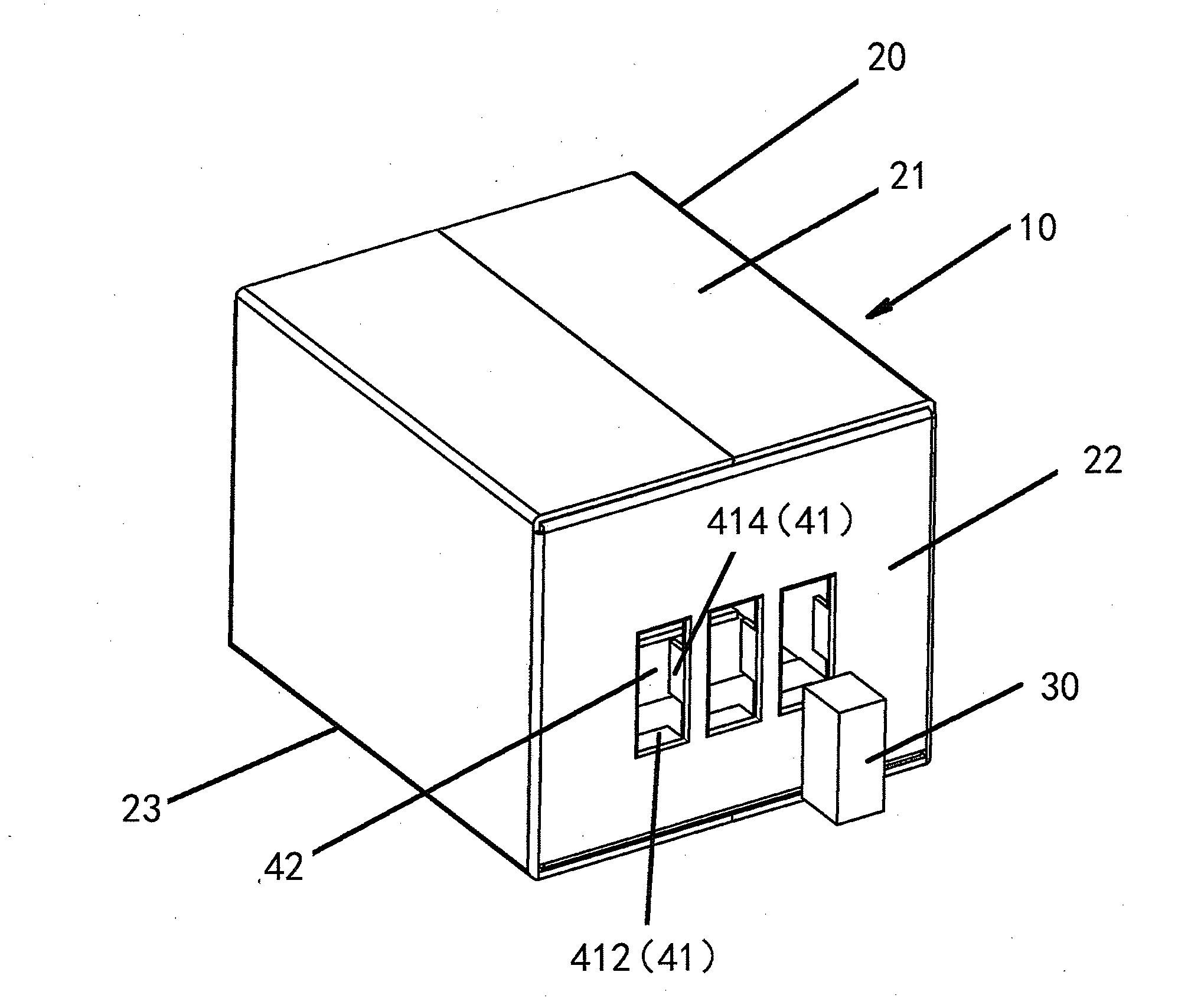
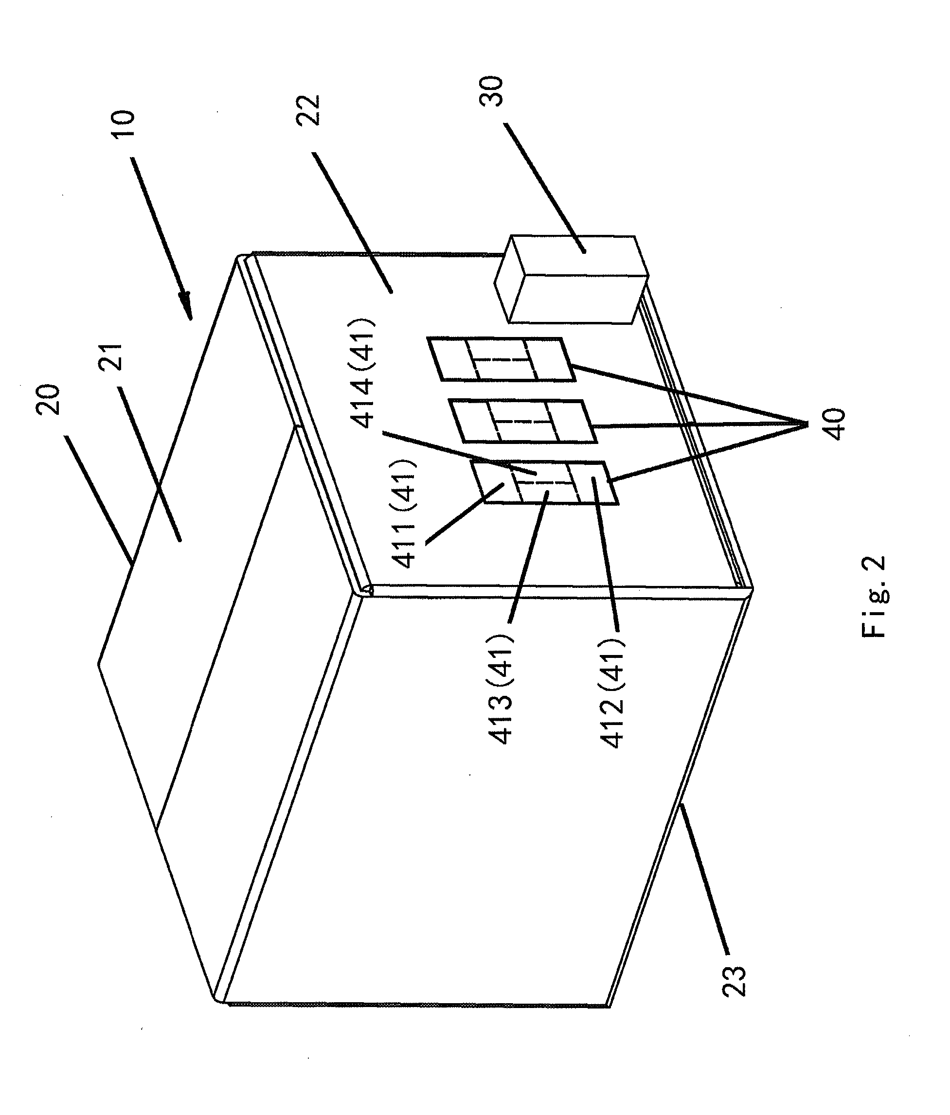
[0040]Referring to FIGS. 2 and 3, in the first embodiment, the upper piece 411, the lower piece 412, the left piece 413 and the right piece 414 each are rectangular; the left and right sides of each of the upper piece 411 and the lower piece 412 are completely cut off; the lower side of the upper piece 411 and the upper side of the lower piece 412 are formed as scores; and the intermediate side between the left piece 413 and the right piece 414 is formed as a score. With the above configuration, the distributor can cut off the scores easily by hand, and then fold the respective folding pieces 41 inward to the inside of the external packing carton 20 so as to open the opening 42 in the side surface 22 of the external packing carton 20. Since the opening 42 is easy to be opened and the small packing carton 30 can be easily inserted, the packing can be easily conducted.

[0041]Alternatively, the left and right sides of each of the upper piece 411 and the lower piece 412 can be formed as ...

third embodiment

[0048]FIG. 6 is a schematic view of a packing structure according to the present invention, in which a folding portion forms an opening.

[0049]As shown in FIG. 6, the folding piece 41 is provided with a stopping part 101 on a side thereof opposite to a side surface 22 of the external packing carton 20. When the small packing carton 30 is inserted into the opening 42, the small packing carton 30 is stopped by the stopping part 101 and is not able to be inserted further. For example, even if there is a large distance between an outer side of the buffering material 50 (shown in FIG. 5) and an inner side of the external packing carton 20, in other words, even if there is a large distance between the ventilating fan machine 100 and the external packing carton 20 for inserting the small packing carton 30, the small packing carton 30 can be prevented from being inserted into the external packing carton 20 too much.

[0050]Therefore, the small packing carton 30 can be disposed in the opening 4...


PUM

PropertyMeasurementUnit
Thicknessaaaaaaaaaa
Structureaaaaaaaaaa
Sizeaaaaaaaaaa

Abstract

A packing structure including an external packing carton consisting of a top surface, a bottom surface and side surfaces connected with one another and one or more small packing cartons, wherein at least one side surface of the external packing carton is provided with one or more folding portions, each folding portion consisting of one or more folding pieces which are folded to form an opening with a size mating with the size of the periphery of the small packing carton. The packing structure of the present disclosure is easy to be transported, cost reducing and friendly to the environment.

Description

CROSS-REFERENCE TO RELATED APPLICATION[0001]This application claims the benefit of Chinese Patent Application No. 201320807555.8 filed on Dec. 9, 2013in the State Intellectual Property Office of China, the whole disclosure of which is incorporated herein by reference.BACKGROUND OF THE INVENTION[0002]1. Field of the Invention[0003]The present invention relates to a packing structure.[0004]2. Description of the Related Art[0005]Packing cartons are commonly used to packing various articles. FIG. 1 is a schematic view of a packing carton in the prior art. The packing carton in FIG. 1 is shown to pack a ventilating fan as an example.[0006]Ventilating fans are commonly-used apparatuses mounted between a ceiling and a roof for ventilating. There is a kind of ventilating fan in the art, by which a customer can choose to buy only a ventilating fan machine or to buy a ventilating fan machine together with one or more functional units freely mountable to the ventilating fan machine. The ventil...

Claims


Application Information

Patent Timeline
IPC IPC(8): B65D21/02B65D85/68
CPCB65D85/68B65D21/0202B65D21/0237B65D2585/6807
Inventor HOU, GUANCHENGZHONG, BODONGGAO, SHOUYONGTSUBOSA, DAISUKE
Owner PANASONIC ECOLOGY SYSTEMS GUANGDONG CO LTD
Why Eureka
Try Eureka