Linear LED Illumination Device with Improved Color Mixing

a technology of led illumination and color mixing, which is applied in the direction of lighting support devices, lighting and heating apparatus, light source combinations, etc., can solve the problems of poor color mixing in the far field, and the light radiated from the dome cannot be perfectly mixed, so as to achieve the effect of improving color mixing, maintaining precise and uniform color over time, and not using excessively large optics or optical losses

Active Publication Date: 2015-06-11
LUTRON TECH CO LLC
View PDF4 Cites 27 Cited by
  • Summary
  • Abstract
  • Description
  • Claims
  • Application Information

AI Technical Summary

Benefits of technology

[0013]A linear multi-color LED illumination device that produces a light beam with uniform color throughout the output beam without the use of excessively large optics or optical losses is disclosed herein. In addition to improved color mixing, the illumination device includes a light detector and optical feedback for maintaining precise and uniform color over time and / or with changes in temperature. The illumination device described herein may also be referred to as a light, luminaire or lamp.
[0017]In general, an illumination device in accordance with the present invention may include at least a first emitter module, a second emitter module, and a third emitter module arranged in a line, wherein the second emitter module is spaced equally distant between the first and third emitter modules. To improve color mixing, the second emitter module may be rotated X degrees relative to the first emitter module, and the third emitter module may be rotated 2X degrees relative to the first emitter module. X may be substantially any rotational angle equal to 360 degrees divided by an integer N, where N is greater than or equal to 3.
[0018]In some embodiments, color mixing may be further improved by covering each emitter module with an optically transmissive dome, whose shallow or flattened shape allows a significant amount of light emitted by the LED array to escape out of the side of the emitter module. For example, a shallow dome may be formed with a radius in a plane of the LED array that is about 20-30% larger than the radius of the curvature of the shallow dome. Such a shape may enable approximately 40% of the light emitted by the LED array to exit the shallow dome at small angles (e.g., approximately 0 to 30 degrees) relative to the plane of the LED array.

Problems solved by technology

Although such a product may exhibit good color mixing in the far field, it does not exhibit good color mixing in the near field.
However, depending on the size of the primary and secondary optics, the far field color mixing may actually be worse in products that package multiple colors of LEDs together.
Since the different colored LEDs are in physically different locations within the hemispherical silicone dome, the light radiated from the dome, and therefore, from the TIR optical element will not be perfectly mixed.
Although larger domes and larger TIR optical elements may be used to provide better color mixing, there are practical limits to the size of these components, and consequently, to the near and far field color mixing provided by such an approach.
Although such systems can achieve very good color mixing in both the near and the far field, there is a tradeoff between color mixing and optical efficiency.
Multi-color LED linear lights with TIR optics on each individual LED cannot achieve good color mixing in the near field.
Multi-color LED linear lights that use conventional diffusers and reflectors to achieve good color mixing in both the near and the far field suffer optical losses.

Method used


Image

  • Linear LED Illumination Device with Improved Color Mixing
  • Linear LED Illumination Device with Improved Color Mixing
  • Linear LED Illumination Device with Improved Color Mixing

Examples


Embodiment Construction

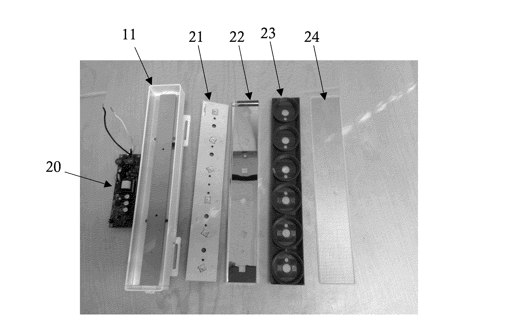
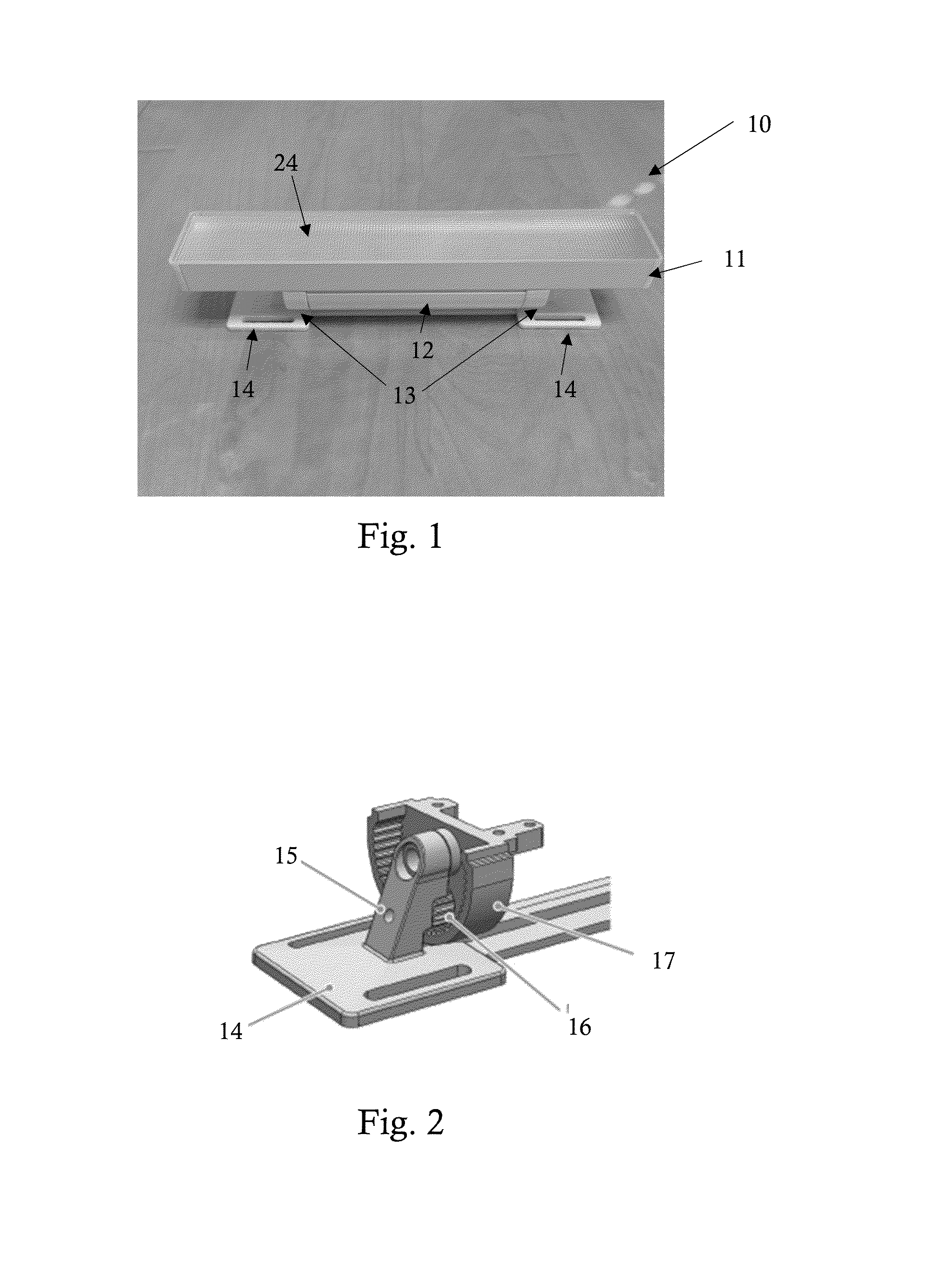
[0047]Turning now to the drawings, FIG. 1 is a picture of a linear LED lamp 10, according to one embodiment of the invention. As described in more detail below, linear LED lamp 10 produces light over a wide color gamut, thoroughly mixes the color components within the output beam, and uses an optical feedback system to maintain precise color over LED lifetime, and in some cases, with changes in temperature. The linear LED lamp 10 shown in FIG. 1 is powered by the AC mains, but may be powered by alternative power sources without departing from the scope of the invention. The light beam produced by LED lamp 10 can be symmetric or asymmetric, and can have a variety of beam angles including, but not limited to, 120×120, 60×60, and 60×30. If an asymmetric beam is desired, the asymmetric beam typically has a wider beam angle across the length of the lamp.

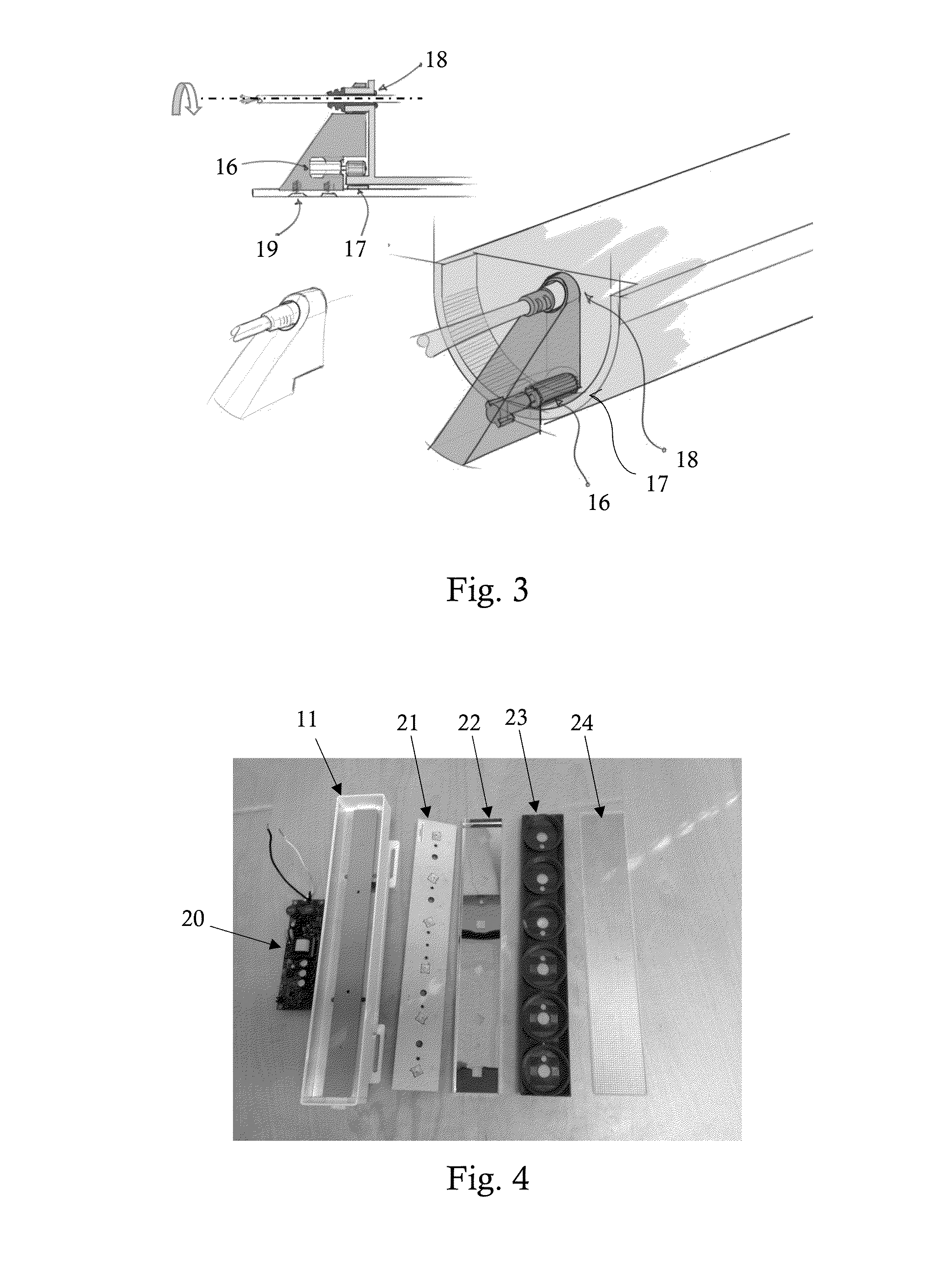
[0048]In general, LED lamp 10 comprises emitter housing 11, power supply housing 12, and rotating hinges 13. As shown more clearly in FI...


PUM


Abstract

A linear multi-color LED illumination device that produces uniform color throughout the output light beam without the use of excessively large optics or optical losses is disclosed herein. Embodiments for improving color mixing in the linear illumination device include, but are not limited to, a shallow dome encapsulating a plurality of emission LEDs within an emitter module, a unique arrangement of a plurality of such emitter modules in a linear light form factor, and special reflectors designed to improve color mixing between the plurality of emitter modules. In addition to improved color mixing, the illumination device includes a light detector and optical feedback for maintaining precise and uniform color over time and / or with changes in temperature. The light detector is encapsulated within the shallow dome along with the emission LEDs and is positioned to capture the greatest amount of light reflected by the dome from the LED having the shortest emission wavelength.

Description

RELATED APPLICATIONS[0001]This application is related to the following co-pending applications: U.S. patent application Ser. No. ______; U.S. patent application Ser. Nos. 13 / 970,944; 13 / 970,964; 13 / 970,990; 12 / 803,805; and 12 / 806.118; each of which is hereby incorporated by reference in its entirety.BACKGROUND[0002]1. Field of the Invention[0003]The invention relates to the addition of color mixing optics and optical feedback to produce uniform color throughout the output light beam of a multi-color linear LED illumination device.[0004]2. Description of Related Art[0005]Multi-color linear LED illumination devices (also referred to herein as lights, luminaires or lamps) have been commercially available for many years. Typical applications for linear LED illumination devices include wall washing in which a chain of lights attempt to uniformly illuminate a large portion of a wall, and cove lighting in which a chain of lights typically illuminates a large portion of a ceiling Multi-colo...

Claims


Application Information

Patent Timeline
Patent Type & Authority Applications(United States)
IPC IPC(8): F21K99/00H05B33/08H05B44/00
CPCH05B33/0854F21K9/54F21V7/0083F21V7/048F21V7/06F21V13/04F21V21/30F21Y2105/12F21Y2105/10F21K9/62F21Y2115/10F21Y2113/17F21Y2103/10H05B45/20H05B45/00H05B45/28H05B45/18H05B45/10H05B45/22F21Y2103/00
Inventor DONG, FANGXUPHILLIPS, CRAIG T.KNAPP, DAVID J.
Owner LUTRON TECH CO LLC
Why Eureka
Try Eureka