Lighting device with multi-chip light emitters, solid state light emitter support members and lighting elements

a light emitter and multi-chip technology, applied in the field of light emitters, can solve the problems of incandescent light bulbs being very energy-inefficient light sources, incandescent light bulbs having relatively short lifetimes, and still less efficient than solid-state light emitters such as light emitting diodes, and achieve excellent color mixing and color mixing benefits

Active Publication Date: 2013-08-13
IDEAL IND LIGHTING LLC
View PDF120 Cites 21 Cited by
  • Summary
  • Abstract
  • Description
  • Claims
  • Application Information

AI Technical Summary

Benefits of technology

[0032]It has been found that surprisingly effective color mixing (and hence surprisingly good color uniformity of emitted light beam) can be achieved by spatially offsetting one or more multi-chip light emitters such that solid state light emitters on different light emitters that emit light of respective hues that are within seven MacAdams ellipses of each other are oriented differently relative to the other solid state light emitters on the respective multi-chip light emitters.
[0034]In some embodiments, one or more collimating total internal reflection (TIR) lenses can be employed, and the benefits in color mixing provided by the present inventive subject matter are exceptional because lenslets provided on the surface of the lenses do not, by themselves, achieve adequate color mixing, but offsetting multi-chip light emitters as described herein enables excellent color mixing to be achieved.

Problems solved by technology

It is well known that incandescent light bulbs are very energy-inefficient light sources—about ninety percent of the electricity they consume is released as heat rather than light.
Fluorescent light bulbs are more efficient than incandescent light bulbs (by a factor of about 10) but are still less efficient than solid state light emitters, such as light emitting diodes.
In addition, as compared to the normal lifetimes of solid state light emitters, e.g., light emitting diodes, incandescent light bulbs have relatively short lifetimes, i.e., typically about 750-1000 hours.
Fluorescent bulbs generally have lifetimes that are longer than those of incandescent lights (e.g., some fluorescent bulbs have reported lifetimes of 10,000-20,000 hours), but they typically provide less favorable color reproduction.
The impact of the need to replace light emitters is particularly pronounced where access is difficult (e.g., vaulted ceilings, bridges, high buildings, highway tunnels) and / or where change-out costs are extremely high.

Method used


Image

  • Lighting device with multi-chip light emitters, solid state light emitter support members and lighting elements
  • Lighting device with multi-chip light emitters, solid state light emitter support members and lighting elements
  • Lighting device with multi-chip light emitters, solid state light emitter support members and lighting elements

Examples


example

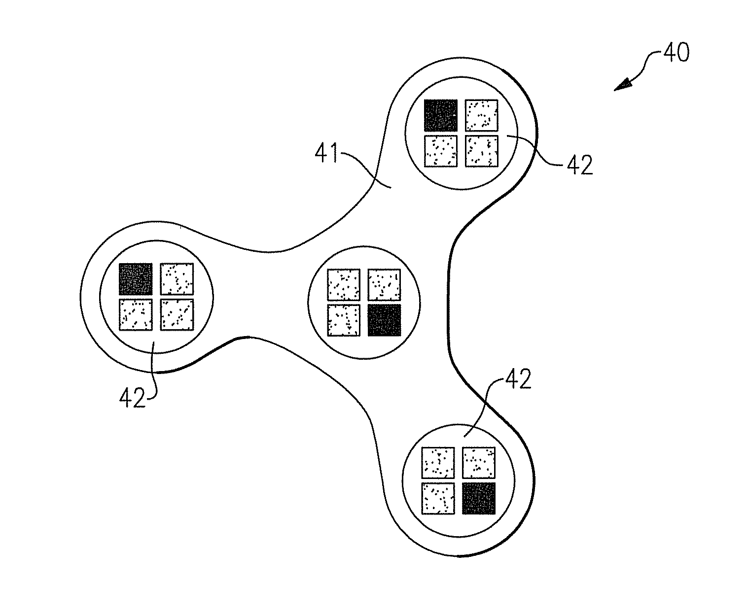
[0435]Tests were conducted using a Fraen optic and an Apollo lamp, and it was found that the orientation of the multi-chip light emitters (in a 2×2 array with three BSY solid state light emitters and one red solid state light emitter) with respect to each other had a significant impact on color uniformity.

[0436]A first prototype assembled had seven multi-chip light emitters (arranged as depicted in FIG. 8), each with the red solid state light emitter 81 in the same spatial location in each multi-chip light emitter, namely, in the bottom right (and the BSY solid state light emitters 82 in the top right, bottom left and bottom right).

[0437]In this configuration, the beam exhibited a color non-uniformity that was clearly visible to the naked eye. However, by rotating at three out of the seven multi-chip light emitters (namely, the multi-chip light emitter in the top row on the right side, the multi-chip light emitter in the middle row on the left side, and the multi-chip light emitter ...


PUM


Abstract

A lighting device in which a solid state light emitter in a first multi-chip light emitter is spatially offset relative to a solid state light emitter in a second multi-chip light emitter. A lighting device comprising first, second and third multi-chip light emitters, in which any solid state light emitter in the second multi-chip light emitter that is spatially offset relative to a first solid state light emitter on the first multi-chip light emitter by less than 10 degrees emits light of a hue that differs from the hue of light emitted by the first solid state light emitter by more than seven MacAdam ellipses. A solid state light emitter support member comprising a center region and at least first, second and third protrusions extending from the center region. A lighting device comprising at least a first housing member, and means for emitting substantially uniform light.

Description

CROSS-REFERENCE TO RELATED APPLICATIONS[0001]This application claims the benefit of U.S. Provisional Patent Application No. 61 / 298,701, filed Jan. 27, 2010, the entirety of which is incorporated herein by reference.[0002]This application claims the benefit of U.S. Provisional Patent Application No. 61 / 299,154, filed Jan. 28, 2010, the entirety of which is incorporated herein by reference.[0003]This application claims the benefit of U.S. Provisional Patent Application No. 61 / 299,183, filed Jan. 28, 2010, the entirety of which is incorporated herein by reference.[0004]This application claims the benefit of U.S. Provisional Patent Application No. 61 / 299,634, filed Jan. 29, 2010, the entirety of which is incorporated herein by reference.FIELD OF THE INVENTIVE SUBJECT MATTER[0005]The present inventive subject matter is directed to lighting devices that comprise one or more multi-chip light emitters, e.g., multi-chip solid state light emitters. The present inventive subject matter is also...

Claims


Application Information

Patent Timeline
Patent Type & Authority Patents(United States)
IPC IPC(8): F21V9/00F21V21/00F21V15/01
CPCF21K9/00F21K9/137F21V5/04F21V7/0091F21Y2101/02F21Y2105/003F21Y2113/005F21K9/233F21K9/62F21Y2105/10F21Y2105/12F21Y2113/13F21Y2115/10
Inventor NEGLEY, GERALD H.EDMOND, MARKPICKARD, PAUL KENNETH
Owner IDEAL IND LIGHTING LLC
Why Eureka
Try Eureka