Delivery devices, systems and methods for stimulating nerve tissue on multiple spinal levels

a delivery device and spinal cord technology, applied in the field of delivery devices, systems and methods for stimulating nerve tissue on multiple spinal cord levels, can solve the problems of uncontrollable amount of stimulation energy needed to provide the desired amount of neurostimulation, unsatisfactory stimulation of motor nerves, and further altering local neural excitability states, so as to reduce deleterious side effects and effectively treat pain symptoms

Active Publication Date: 2015-06-18
TC1 LLC
View PDF3 Cites 20 Cited by
  • Summary
  • Abstract
  • Description
  • Claims
  • Application Information

AI Technical Summary

Benefits of technology

The present invention is about devices, systems, and methods that can stimulate the spinal anatomy at different locations, like spinal levels. This allows for targeted treatment of pain and reduction of side effects. The devices can create a single access path to an implantable pulse generator (IPG) which reduces procedure complexity, time, and recovery. The invention can also be used to stimulate other portions of the spine or other anatomies.

Problems solved by technology

Although such SCS systems have effectively relieved pain in some patients, these systems have a number of drawbacks.
Accordingly, electrical stimulation by the lead 14 often causes undesirable stimulation of the motor nerves in addition to the sensory spinal nervous tissue.
Moreover, these and other conventional, non-specific stimulation systems also apply stimulation energy to the spinal cord and to other neural tissue beyond the intended stimulation targets.
Moreover, larger epidural electrode arrays may alter cerebral spinal fluid flow thus further altering local neural excitability states.
Another challenge confronting conventional neurostimulation systems is that since epidural electrodes must apply energy across a wide variety of tissues and fluids (i.e. CSF fluid amount varies along the spine as does pia mater thickness) the amount of stimulation energy needed to provide the desired amount of neurostimulation is difficult to precisely control.
However, as applied stimulation energy increases so too increases the likelihood of deleterious damage or stimulation of surrounding tissue, structures or neural pathways.

Method used


Image

  • Delivery devices, systems and methods for stimulating nerve tissue on multiple spinal levels
  • Delivery devices, systems and methods for stimulating nerve tissue on multiple spinal levels
  • Delivery devices, systems and methods for stimulating nerve tissue on multiple spinal levels

Examples


Embodiment Construction

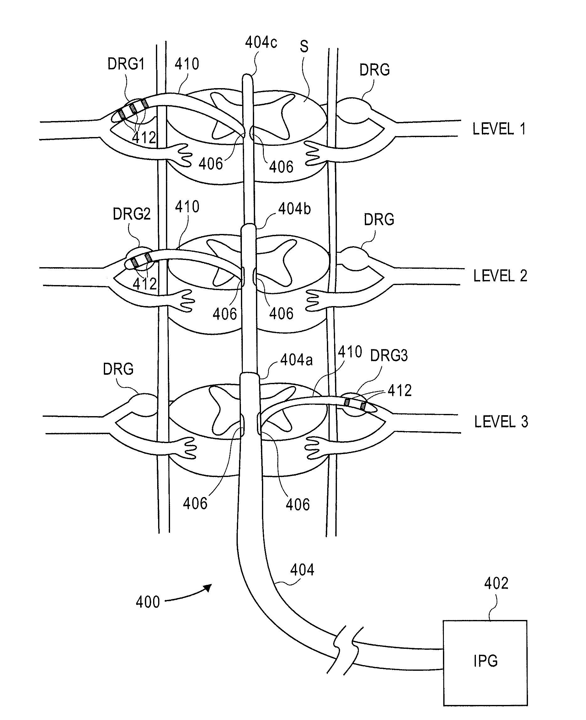
[0049]In preferred embodiments, the devices, systems and methods stimulate the various spinal levels at specific nerve anatomies, such as the dorsal root DR or more specifically the dorsal root ganglion DRG. The following examples will illustrate specific stimulation of the dorsal root ganglia of various levels, however the embodiments are not so limited. Also, the following examples utilize various types of leads to provide stimulation. It may be appreciated that other elements, such as agent delivery devices, may be used alternatively or in addition to the leads for delivery of an agent to a specific nerve anatomy.

[0050]FIG. 6 illustrates positioning of a device 400 of the present invention so as to optionally simultaneously stimulate various levels (levels 1, 2, 3 in this example) of the spinal cord S. The device 400 is shown positioned within an epidural space of the spinal column, residing against the dura layer of the spinal cord. This is achieved by inserting the device throu...


PUM


Abstract

Devices, systems and methods are provided for simultaneously stimulating the spinal anatomy at various locations, such as spinal levels, along the spinal cord. By stimulating multiple levels of the spinal column with the use of a single device, a single access path is created to an implantable pulse generator (IPG) rather than individual access paths for each lead at each spinal level to an IPG. By reducing the number of pathways, the procedure complexity, time and recovery are reduced. In addition, some embodiments provide additional specificity within each targeted level, such as selective stimulation of specific tissue, such as the dorsal root ganglion.

Description

CROSS-REFERENCES TO RELATED APPLICATIONS[0001]This application is a divisional of U.S. patent application Ser. No. 11 / 952,053, filed Dec. 6, 2007, titled “DELIVERY DEVICES, SYSTEMS AND METHODS FOR STIMULATING NERVE TISSUE ON MULTIPLE SPINAL LEVELS,” now U.S. Patent Application Publication No. 2008-0140169-A1, which claims the benefit of U.S. Provisional Patent Application No. 60 / 873,535, filed Dec. 6, 2006, titled “GROUPED LEADS FOR POSTERIOR ACCESS OF DIRECTED SPINAL STIMULATION” and U.S. Provisional Patent Application No. 60 / 873,464, filed Dec. 6, 2006, and titled “GROUPED LEADS FOR SPINAL STIMULATION,” each of which are incorporated herein by reference for all purposes.STATEMENT AS TO RIGHTS TO INVENTIONS MADE UNDER FEDERALLY SPONSORED RESEARCH AND DEVELOPMENT[0002]Not applicable.REFERENCE TO A “SEQUENCE LISTING,” A TABLE, OR A COMPUTER PROGRAM LISTING APPENDIX SUBMITTED ON A COMPACT DISK.[0003]Not applicable.BACKGROUND OF THE INVENTION[0004]The application of specific electrical...

Claims


Application Information

Patent Timeline
Patent Type & Authority Applications(United States)
IPC IPC(8): A61N1/05
CPCA61N1/0551A61N1/0558A61N1/36062A61N1/05A61N1/3605A61N1/36071
Inventor IMRAN, MIR A.
Owner TC1 LLC
Why Eureka
Try Eureka