
Low-pressure turbine

Inactive Publication Date: 2015-06-18
SIEMENS AG
View PDF1 Cites 1 Cited by
  • Summary
  • Abstract
  • Description
  • Claims
  • Application Information

AI Technical Summary

Benefits of technology

The invention proposes a new outer housing for a two-flow low-pressure partial turbine that allows for an axial discharge flow, reducing the cost of the machine housing. This design also helps to harmonize basic power plants, resulting in significant cost savings.

Problems solved by technology

An axial arrangement of the individual partial turbines in succession requires a comparatively large amount of installation space.
This generally leads to an increased space requirement, since low-pressure partial turbines configured in this way have to be constructed either with a great width or with a great height.
In particular, in the case of a Single Side Exhaust assembly, the pipe system is concentrated on one side, and might therefore lead to problems in terms of space.

Method used


Image

  • Low-pressure turbine
  • Low-pressure turbine

Examples


Embodiment Construction

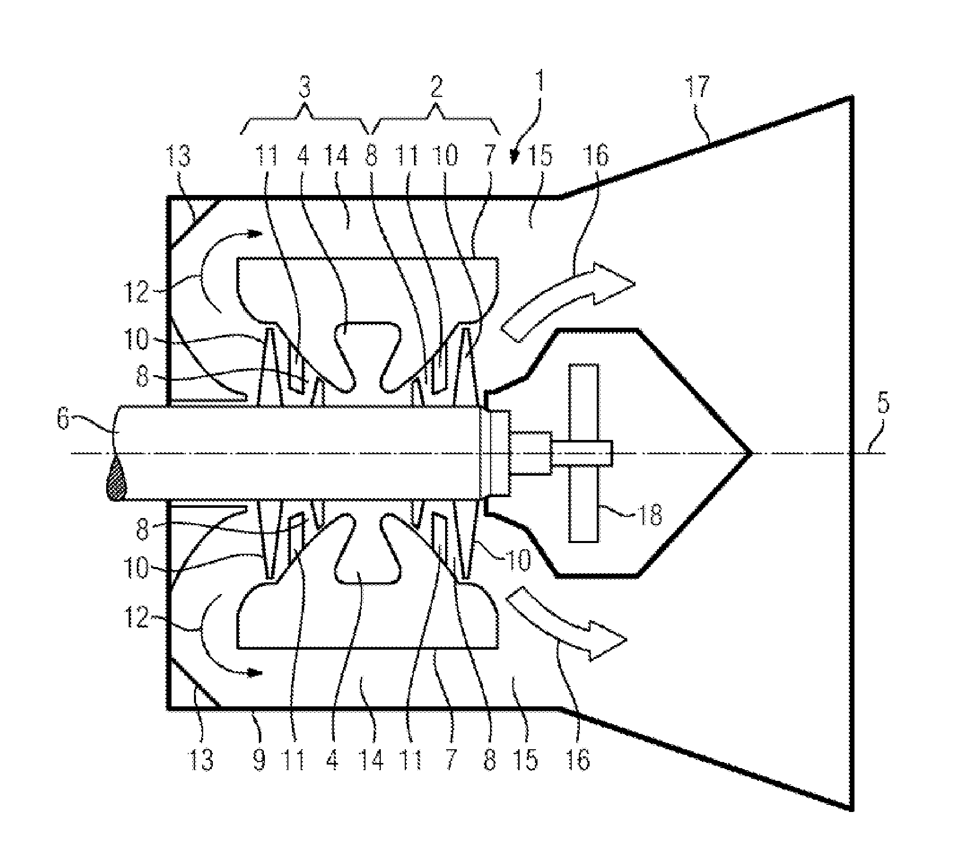
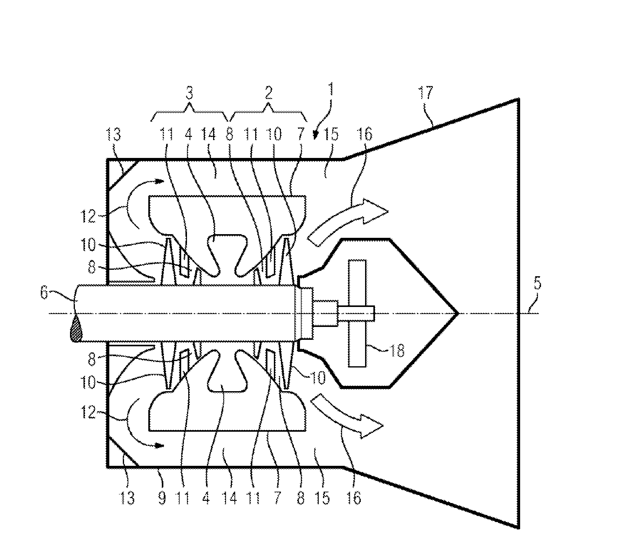
[0014]The FIGURE shows a low-pressure partial turbine 1, which has a two-flow configuration. This means that the low-pressure partial turbine 1 has a first flow 2 and a second flow 3. Live steam flows into the low-pressure partial turbine 1 via an admission connector 4. A flow path 8 is formed between a rotor 6 mounted rotatably about an axis of rotation 5 and an inner housing 7 arranged around the rotor 6.

[0015]An outer housing 9 is arranged around the inner housing 7. The rotor 6 is formed with individual rotor blades 10. For the sake of clarity, only one rotor blade is provided with the reference sign 10. Guide vanes 11 arranged on the inner housing 7 are arranged between the individual rotor blade stages. For reasons of clarity, only one guide vane is provided with the reference sign 11.

[0016]Live steam flows in via the admission connector 4 and is expanded in the first flow 2 to the right, as seen in the plane of the drawing, and in the second flow 3 to the left, as seen in the...


PUM


Abstract

A double-flow low-pressure partial turbine is provided herein, wherein the exhaust steam of the first flow and the exhaust steam of the second flow are deflected in a common direction within the outer housing and thus axial outlet flow occurs.

Description

CROSS REFERENCE TO RELATED APPLICATIONS[0001]This application is the US National Stage of International Application No. PCT / EP2013 / 065466 filed Jul. 23, 2013, and claims the benefit thereof. The International Application claims the benefit of European Application No. EP12178221 filed Jul. 27, 2012. All of the applications are incorporated by reference herein in their entirety.FIELD OF INVENTION[0002]The invention relates to a low-pressure turbine comprising a first flow and a second flow and also a rotor and an inner housing arranged around the rotor and an outer housing arranged around the inner housing. The invention also relates to a method for operating a low-pressure partial turbine, the low-pressure partial turbine having a double-flow configuration.BACKGROUND OF INVENTION[0003]Steam turbines are usually divided into partial turbines. Thus, by way of example, a steam turbine used in local power supply is divided into a high-pressure partial turbine, an intermediate-pressure pa...

Claims


Application Information

Patent Timeline
IPC IPC(8): F01D3/02F01K7/30
CPCF01K7/30F01D3/02F01D25/26F01D25/30F05B2220/301
Inventor BISON, PATRICKVOSS, SEBASTIAN
Owner SIEMENS AG
Learn More