Imaging lens and imaging apparatus

a technology of imaging apparatus and lens, applied in the field of imaging lenses, can solve the problems of difficult difficult to correct favorable chromatic aberration, etc., and achieve the effects of facilitating widening the angle of view of the lens system, facilitating distortion correction, and facilitating spherical aberration correction

Active Publication Date: 2015-06-18
FUJIFILM CORP
View PDF5 Cites 12 Cited by
  • Summary
  • Abstract
  • Description
  • Claims
  • Application Information

AI Technical Summary

Benefits of technology

[0138]Thereby, the advantageous effects below will be exhibited.
[0139]First, disposing a positive lens on the most-object side facilitates correction of distortion.
[0140]Configuring the second lens and the third lens to be negative lenses facilitates widening the angle of view of the lens system.
[0141]Configuring the fourth lens and the fifth lens to be positive lenses facilitates correction of spherical aberration.
[0142]Configuring the value of νd2/νd3 to

Problems solved by technology

The imaging lens disclosed in Patent Document 1 is deemed to have a problem such that correcting chromatic aberrations favorably is difficult.
The imaging lens disclosed in Patent Docu

Method used


Image

  • Imaging lens and imaging apparatus
  • Imaging lens and imaging apparatus
  • Imaging lens and imaging apparatus

Examples


example 1

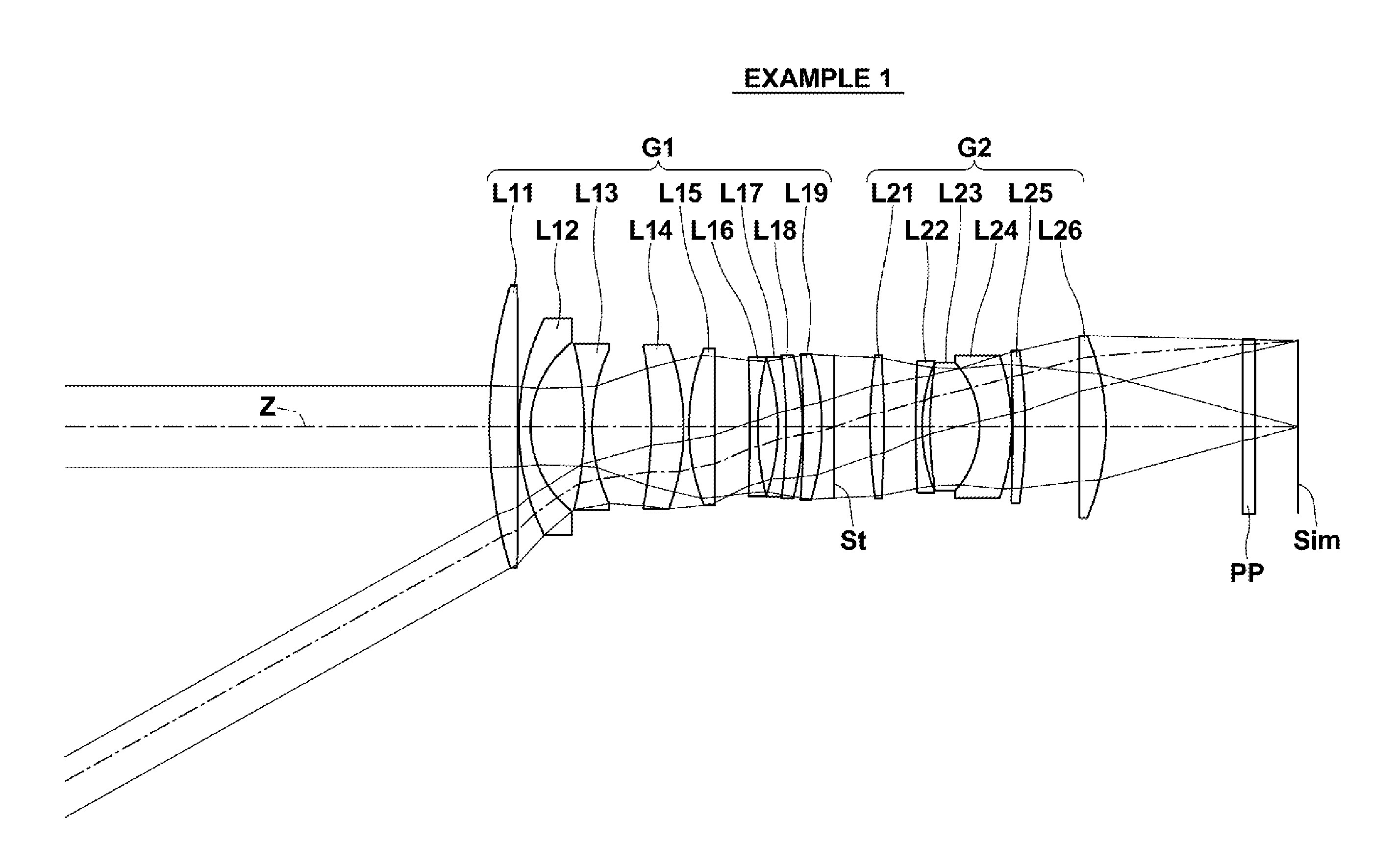
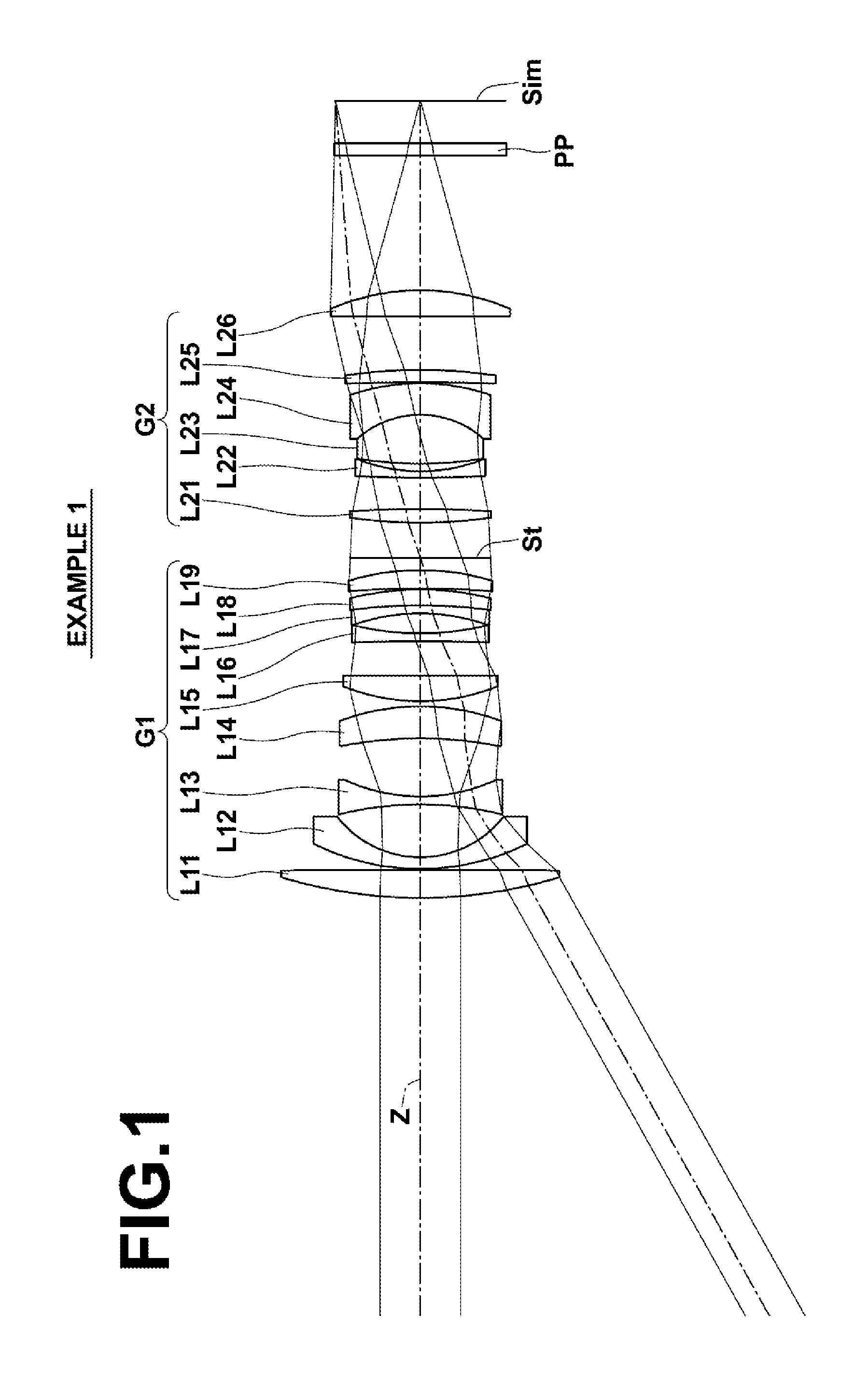
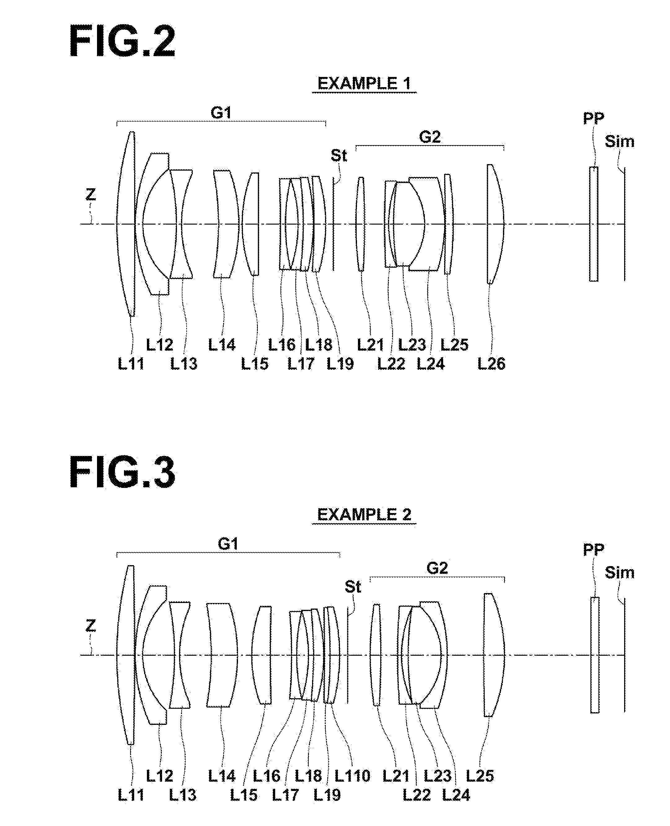
[0234]A cross-sectional view illustrating the lens configuration of an imaging lens of Example 1 is shown in FIG. 2. Referring to FIG. 2, a schematic configuration of the imaging lens of Example 1 will be described. This imaging lens consists of a first lens group G1 having a positive refractive power and a second lens group G2 having a positive refractive power in this order from the object side along the optical axis Z. Focusing is performed by moving the entirety of the second lens group G2 along the optical axis Z.

[0235]The first lens group G1 consists of a positive first lens L11, a negative second lens L12, a negative third lens L13, a positive fourth lens L14, a positive fifth lens L15, a negative sixth lens L16, a negative seventh lens L17, a positive eighth lens L18, and a positive ninth lens L19 in this order from the object side along the optical axis Z. Note that the seventh lens L17 and the eighth lens L18 are cemented to each other.

[0236]Meanwhile, the second lens grou...

example 2

[0312]A cross-sectional view illustrating the lens configuration of an imaging lens of Example 2 is shown in FIG. 3. Referring to FIG. 3, a schematic configuration of the imaging lens of Example 2 will be described. This imaging lens consists of a first lens group G1 having a positive refractive power and a second lens group G2 having a positive refractive power in this order from the object side along the optical axis Z. Focusing is performed by moving the entirety of the second lens group G2 along the optical axis Z.

[0313]The first lens group G1 consists of a positive first lens L11, a negative second lens L12, a negative third lens L13, a positive fourth lens L14, a positive fifth lens L15, a negative sixth lens L16, a negative seventh lens L17, a positive eighth lens L18, a positive ninth lens L19, and a positive tenth lens L110 in this order from the object side along the optical axis Z. Note that the seventh lens L17 and the eighth lens L18 are cemented to each other, and the ...

example 3

[0338]A cross-sectional view illustrating the lens configuration of an imaging lens of Example 3 is shown in FIG. 4. Referring to FIG. 4, a schematic configuration of the imaging lens of Example 3 will be described. This imaging lens consists of a first lens group G1 having a positive refractive power and a second lens group G2 having a positive refractive power in this order from the object side along the optical axis Z. Focusing is performed by moving the entirety of the second lens group G2 along the optical axis Z.

[0339]An aperture stop St is disposed between the first lens group G1 and the second lens group G2.

[0340]The number of lenses which respectively constitute the first lens group G1 and the second lens group G2, the lens power arrangement, and the basic shape of each lens are the same as those in the imaging lens of Example 2. Accordingly, the advantageous effects obtained by the number of the lenses, the lens power arrangement, and the basic shape of each lens are the s...


PUM


Abstract

The imaging lens substantially consists of a first lens group having a positive refractive power and a second lens group having a positive refractive power, in which the entire second lens group moves along the optical axis to perform focusing. In the imaging lens, the first lens group comprises a positive first lens, a negative second lens, a negative third lens, a positive fourth lens, and a positive fifth lens in this order from the object side. When the Abbe number of the second lens with respect to the d-line is νd2 and the Abbe number of the third lens with respect to the d-line is νd3, conditional formula (1) below is satisfied:
2.0<νd2/νd3  (1).

Description

CROSS-REFERENCE TO RELATED APPLICATIONS[0001]The present application claims priority under 35 U.S.C. §119 to Japanese Patent Application No. 2013-260969, filed on Dec. 18, 2011 The above application is hereby expressly incorporated by reference, in its entirety, into the present application.BACKGROUND OF THE INVENTION[0002]1. Technical Field[0003]The present invention relates to an imaging lens, and more particularly to an imaging lens that is favorably used for an electronic camera such as a digital camera, a broadcasting camera, a surveillance camera, a movie camera, and the like.[0004]Further, the present invention relates to an imaging apparatus as described above.[0005]2. Description of the Related Art[0006]Conventionally, imaging apparatuses such as video cameras, electronic still cameras, and the like that utilize image sensors such as a CCD (Charge Coupled Device) and a CMOS (Complementary Metal Oxide Semiconductor) as a recording medium are widely put to practical uses. Fur...

Claims


Application Information

Patent Timeline
IPC IPC(8): G02B15/16G02B9/64
CPCG02B9/64G02B15/161G02B13/0015G02B13/006G02B13/06G02B15/1421G02B15/142G02B5/005G02B9/06G02B9/08G02B27/0025
Inventor ASAMI, TARO
Owner FUJIFILM CORP
Why Eureka
Try Eureka