3D display apparatus and pixel array structure thereof

Active Publication Date: 2015-06-18
TCL CHINA STAR OPTOELECTRONICS TECH CO LTD
View PDF2 Cites 0 Cited by
  • Summary
  • Abstract
  • Description
  • Claims
  • Application Information

AI Technical Summary

Benefits of technology

The present invention provides a 3D display apparatus that solves the problem of uneven display quality at both top and bottom viewing angles. This is achieved by designing a pixel array with sub-pixels that have a lower brightness in the first and second minor sections, and a higher brightness in the major section. A phase retarder film is also used, which has phase retarder units that correspond to the pixel rows. Additionally, a light shielding member may be used between adjacent pixel rows, and the position of the phase retarder units can be alternated. The invention also involves dividing the phase retarder film into first and second phase retarder units, and arranging them alternately. The invention also includes cutting a sub-pixel into at least three sections, with the sections at the top and bottom having lower brightness, to ensure consistent 3D display quality at both viewing angles.

Problems solved by technology

The liquid crystal display panel used in a conventional 3D display apparatus generally has a so-called “color wash-out” problem, which means when a user watch the 3D display apparatus at different viewing angles, the user will see that the same image having different color tones.

Method used


Image

  • 3D display apparatus and pixel array structure thereof
  • 3D display apparatus and pixel array structure thereof
  • 3D display apparatus and pixel array structure thereof

Examples


Embodiment Construction

[0029]The following description of each embodiment is referring to the accompanying drawings so as to illustrate practicable specific embodiments in accordance with the present invention. The directional terms described in the present invention, such as upper, lower, front, rear, left, right, inner, outer, side, etc., are only directions referring to the accompanying drawings, so that the used directional terms are used to describe and understand the present invention, but the present invention is not limited thereto.

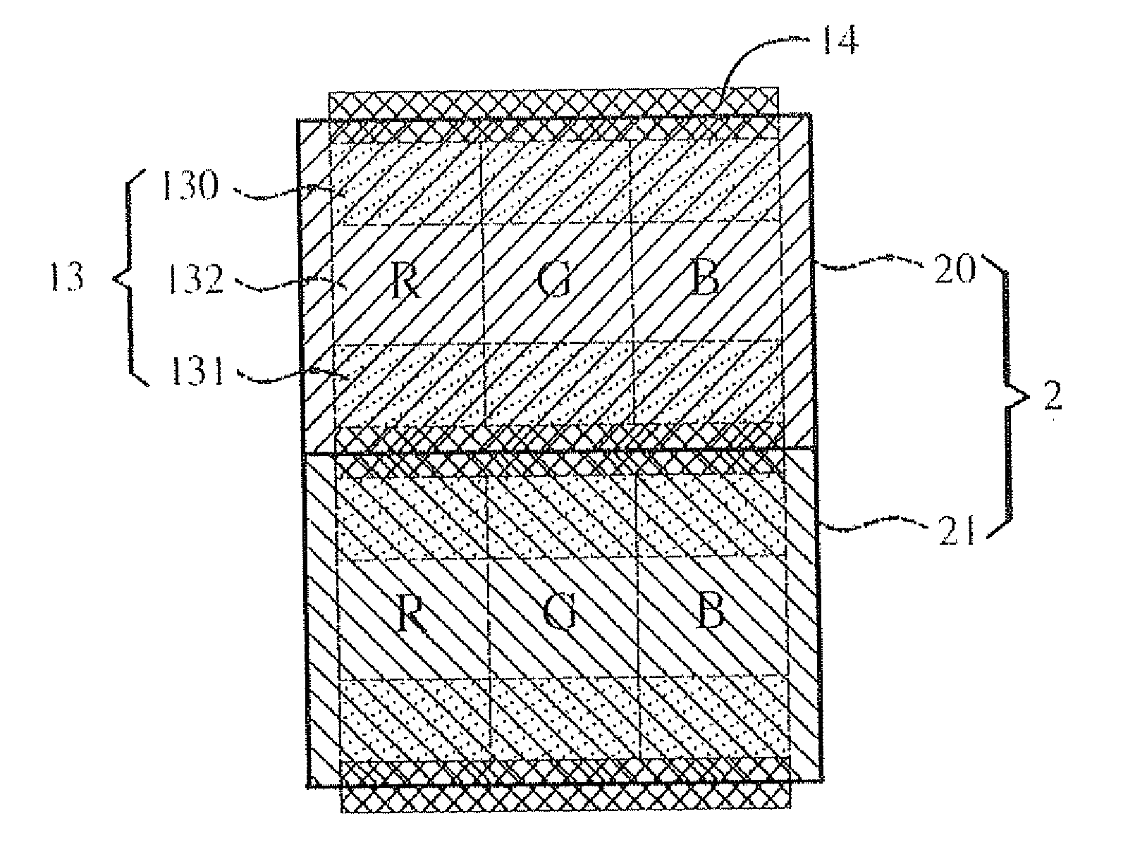
[0030]With reference to FIGS. 4 and 5, a 3D display apparatus in accordance to the present invention comprises a liquid crystal display panel and a phase retarder film 2. Generally speaking, the main structure of the liquid crystal display panel (not illustrated) may include a first substrate, a second substrate, a liquid crystal layer and two polarizers. The first substrate may be a glass substrate or a substrate made from other materials, which has a color filter moun...


PUM


Abstract

A 3D display apparatus and a pixel array structure thereof are disclosed. The pixel array structure has a plurality of pixel rows. Each pixel row has a plurality of sub-pixels. Each sub-pixel has a first minor section, a second minor section and a major section. The major section is disposed between the first minor section and the second minor section. The brightness of the first minor section and the second minor section is lower than that of the major section. The 3D display apparatus can maintain the same display quality at top and bottom view angles.

Description

BACKGROUND OF THE INVENTION[0001]1. Field of the Invention[0002]The present invention relates to the field of display technology, and more particularly to a 3D display apparatus and a pixel array structure thereof.[0003]2. Description of the Related Art[0004]Since there is a distance between the eyes of a person, the eyes each see an object from different directions. Accordingly, a 3D display device provides different images to a person's eyes, respectively, based on binocular disparity, so as to perform a stereoscopic effect.[0005]With reference to FIG. 1, in a conventional 3D display system, lights projected from a liquid crystal display panel of the 3D display system first travel through a polarizer 90 and then turn into linearly polarized lights. The linearly polarized lights then travel through a λ / 4 patterned retarder plate 91. The λ / 4 patterned retarder plate 91 with multiple first phase retarder portions 910 and multiple second phase retarder portions 911 can convert the lin...

Claims


Application Information

Patent Timeline
IPC IPC(8): G02B27/26G02F1/1335G02F1/13363G02F1/1343G02B30/25
CPCG02B27/26G02F1/134309G02F1/133528G02F2001/133541G02F1/133512G02F2001/134345G02F1/13363G02B30/25H04N13/337G02F1/133631
Inventor FAN, DEYONGYANG, CHIHMING
Owner TCL CHINA STAR OPTOELECTRONICS TECH CO LTD
Why Eureka
Try Eureka