Signal transmission/reception method and apparatus therefor
a signal transmission and reception technology, applied in the field of wireless communication systems, can solve problems such as unsatisfactory study of d2d communication schemes including a base station and d2d user equipments, and achieve the effect of efficient transmission and reception, efficient transmission and reception
- Summary
- Abstract
- Description
- Claims
- Application Information
AI Technical Summary
Benefits of technology
Problems solved by technology
Method used
Image
Examples
embodiment 1
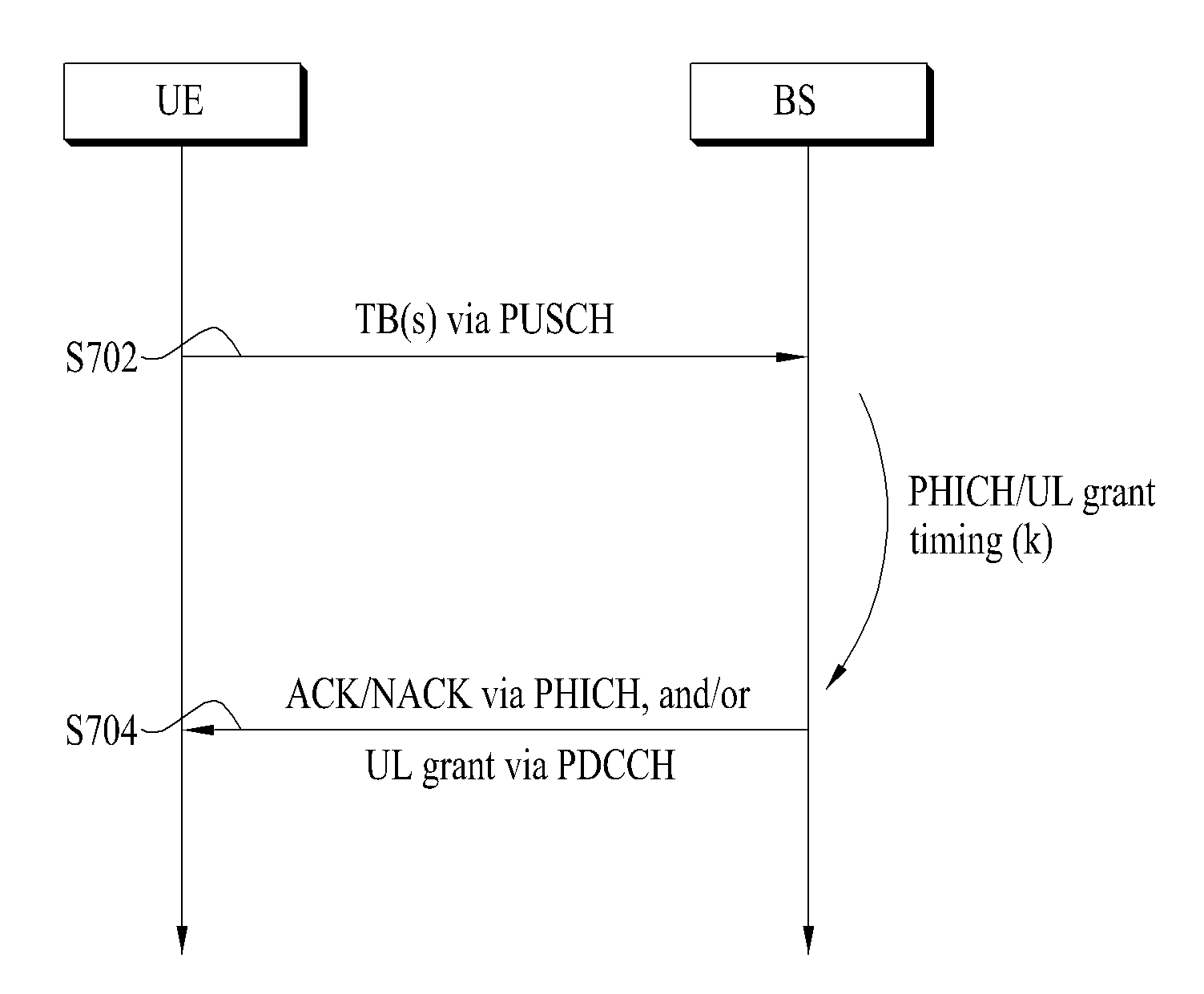
[0112]As mentioned in the foregoing description, since a D2D SPS signal is transmitted to a plurality of unspecified UEs and is periodically transmitted, it may be not necessary to have a retransmission operation for the D2D SPS signal. In particular, it is not necessary to perform a HARQ operation for the D2D SPS signal, which is transceived between D2D UEs 1020 / 1030 / 1040. And, it may be not necessary to transmit an HARQ ACK / NACK signal. Hence, HARQ retransmission for the D2D SPS signal, which is transmitted in the D2D transmitting end 1020, is not performed. Hence, since HARQ ACK / NACK for the D2D SPS signal is not used, it may not use a downlink control channel (e.g., PHICH) for DL ACK / NACK.
[0113]Hence, according to the present embodiment, the D2D transmitting end 1020 does not receive a control channel (e.g., PHICH) for DL ACK / NACK in case of transmitting a D2D SPS signal. And, the D2D transmitting end 1020 can operate as if the D2D transmitting end always receives ACK for a tran...
embodiment 2
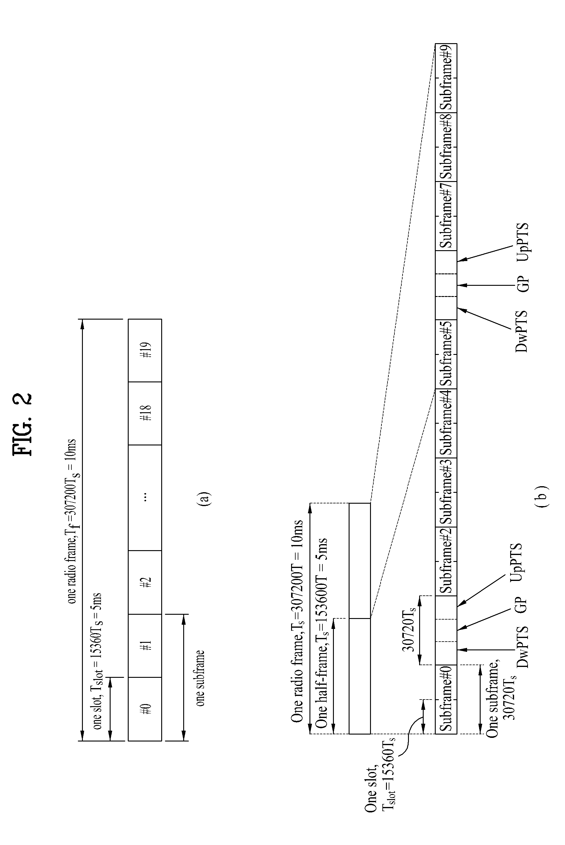
[0114]As mentioned in the foregoing description, since it is not necessary to retransmit a D2D SPS signal, it is not necessary to receive ACK / NACK response in response to the D2D SPS signal. Hence, the D2D SPS signal may have a characteristic (e.g., PHICHless) that it is not necessary to receive ACK / NACK signal (e.g., PHICH). Yet, it may be preferable to use a specific (UL) HARQ process only for D2D SPS signal transmission to avoid collision with a different (UL) HARQ process in case of transmitting the D2D SPS signal. Hence, a transmission period of the D2D SPS signal can be matched with a UL HARQ timeline (e.g., HARQ retransmission period or HARQ RTT) of a legacy LTE system. For instance, matching the transmission period of the D2D SPS signal with the UL HARQ timeline of the legacy LTE system may mean to use a UL subframe corresponding to a specific UL HARQ process only. When the UL subframe corresponding to the specific UL HARQ process is used only to transmit the D2D SPS signal,...
embodiment 3
[0119]FIG. 12 is a diagram for an example of a method of transmitting a D2D SPS signal according to a third embodiment of the present invention. Although FIG. 12 shows a case of FDD system, an identical principle can also be applied to a case of TDD system.
[0120]Referring to FIG. 12(a), a D2D SPS signal may form a massive data in a manner of being bundled by 2, 4 or several units and the massive data can be transmitted. In this case, the bundled D2D SPS signals can be split into a plurality of lower signal units. A plurality of the lower signal units can be transmitted on transmission timings (e.g., subframe) different from each other of a D2D SPS signal transmission period.
[0121]Referring to FIG. 12(b), a D2D SPS signal can be transmitted on transmission timings (e.g., subframe) different from each other of a D2D SPS signal transmission period with RV (redundancy version) values different from each other instead of being bundled. In this case, coverage of the D2D SPS signal may be ...
PUM
 Abstract
Description
Claims
Application Information
 - R&D
- Intellectual Property
- Life Sciences
- Materials
- Tech Scout
- Unparalleled Data Quality
- Higher Quality Content
- 60% Fewer Hallucinations
Browse by: Latest US Patents, China's latest patents, Technical Efficacy Thesaurus, Application Domain, Technology Topic, Popular Technical Reports.
© 2025 PatSnap. All rights reserved.Legal|Privacy policy|Modern Slavery Act Transparency Statement|Sitemap|About US| Contact US: help@patsnap.com


