
Visor

a technology of visors and visors, applied in the field of visors, can solve the problems of camera damage, camera being too big for a team member, and filming from a distance did not provide the necessary views for proper feedback, so as to prevent damage to the camera and prevent breakage

Inactive Publication Date: 2015-06-25
ODELL NICK
View PDF0 Cites 9 Cited by
  • Summary
  • Abstract
  • Description
  • Claims
  • Application Information

AI Technical Summary

Benefits of technology

The invention is a visor with a camera mount that is connected to the upper portion of the visor. The camera mount protects the camera from damage or breakage. The visor can also include a left side and right side portion with the camera mount connected between them. This allows for the secure mounting of a camera on the visor in a safe and secure way.

Problems solved by technology

These cameras are typically mounted on top of a helmet to provide a television viewer with a view similar to what the athlete sees; however, because they are mounted on top of the helmet, they are subject to breakage.
Unfortunately, until recently, cameras were too big to carry on a team member, and filming from a distance did not provide the necessary views for proper feedback.
Today, the cameras have become smaller, but there is still the problem of carrying the camera in a place where it does not interfere with the team members' job.
Like the sports contained in the X-Games format, cameras on top of helmets provide television viewers with an up-close view of how a pit-crew operates, but those cameras can also cause problems by simply catching an air hose during a fast pit stop.

Method used


Image

  • Visor
  • Visor
  • Visor

Examples


Embodiment Construction

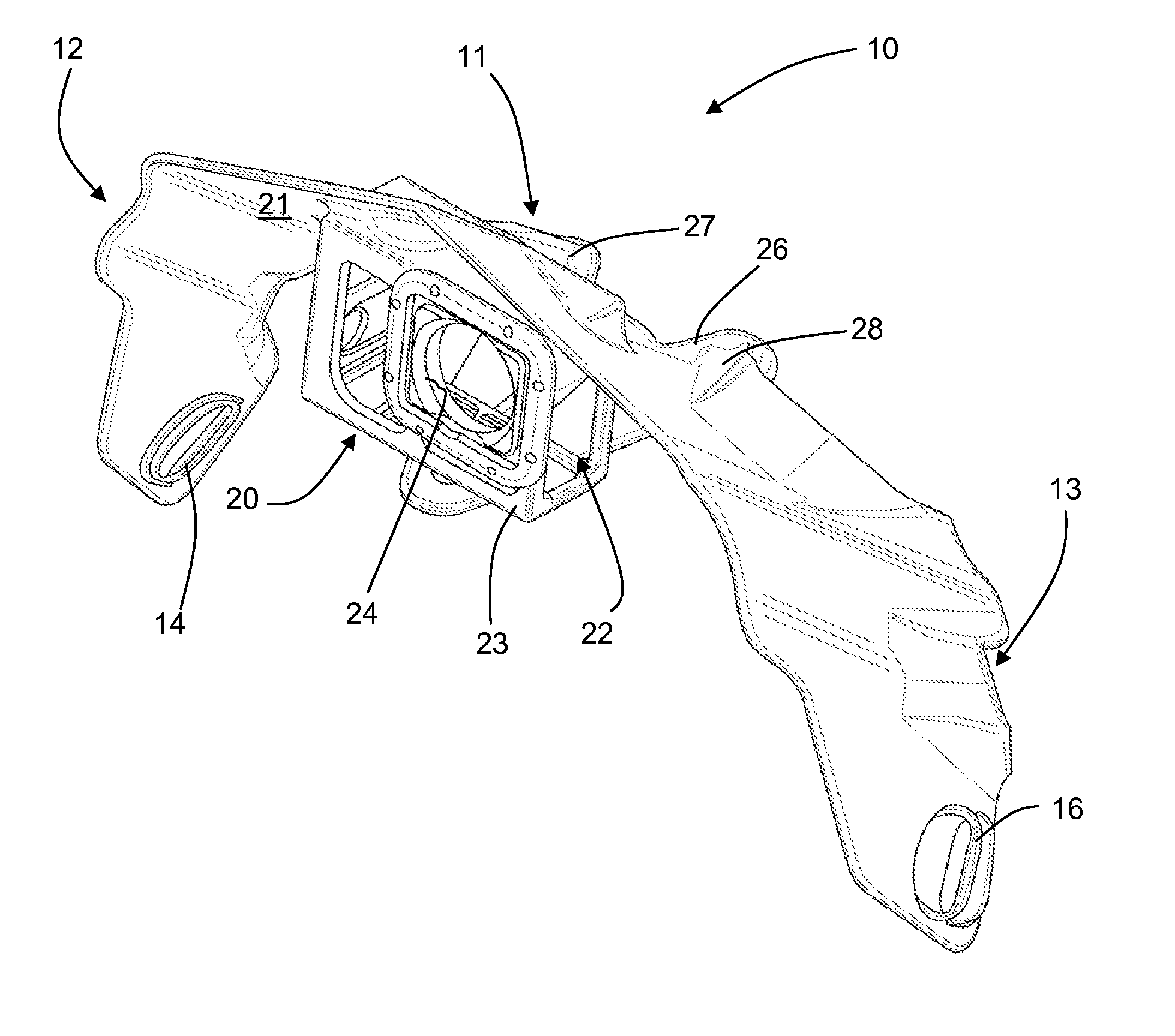
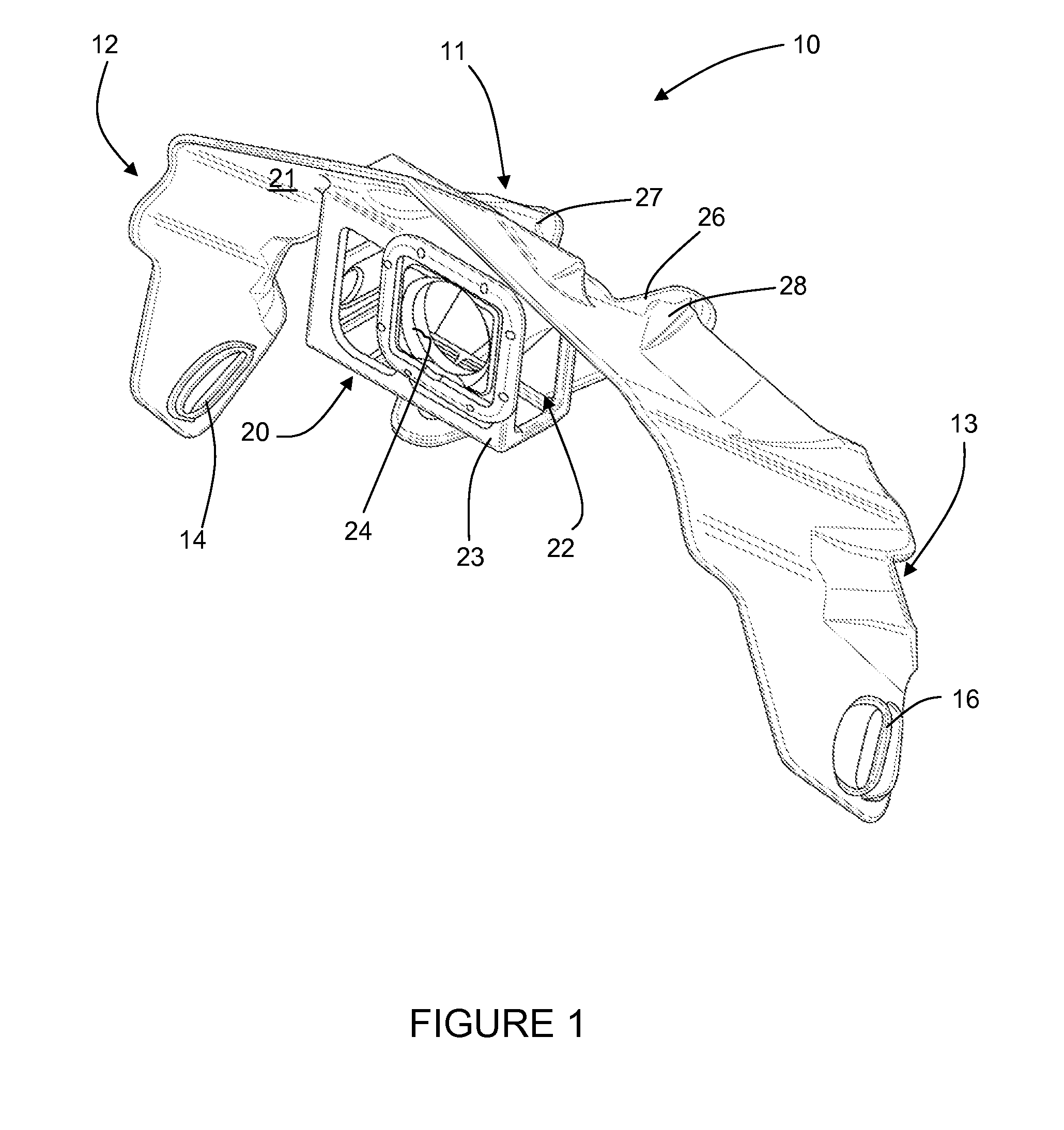
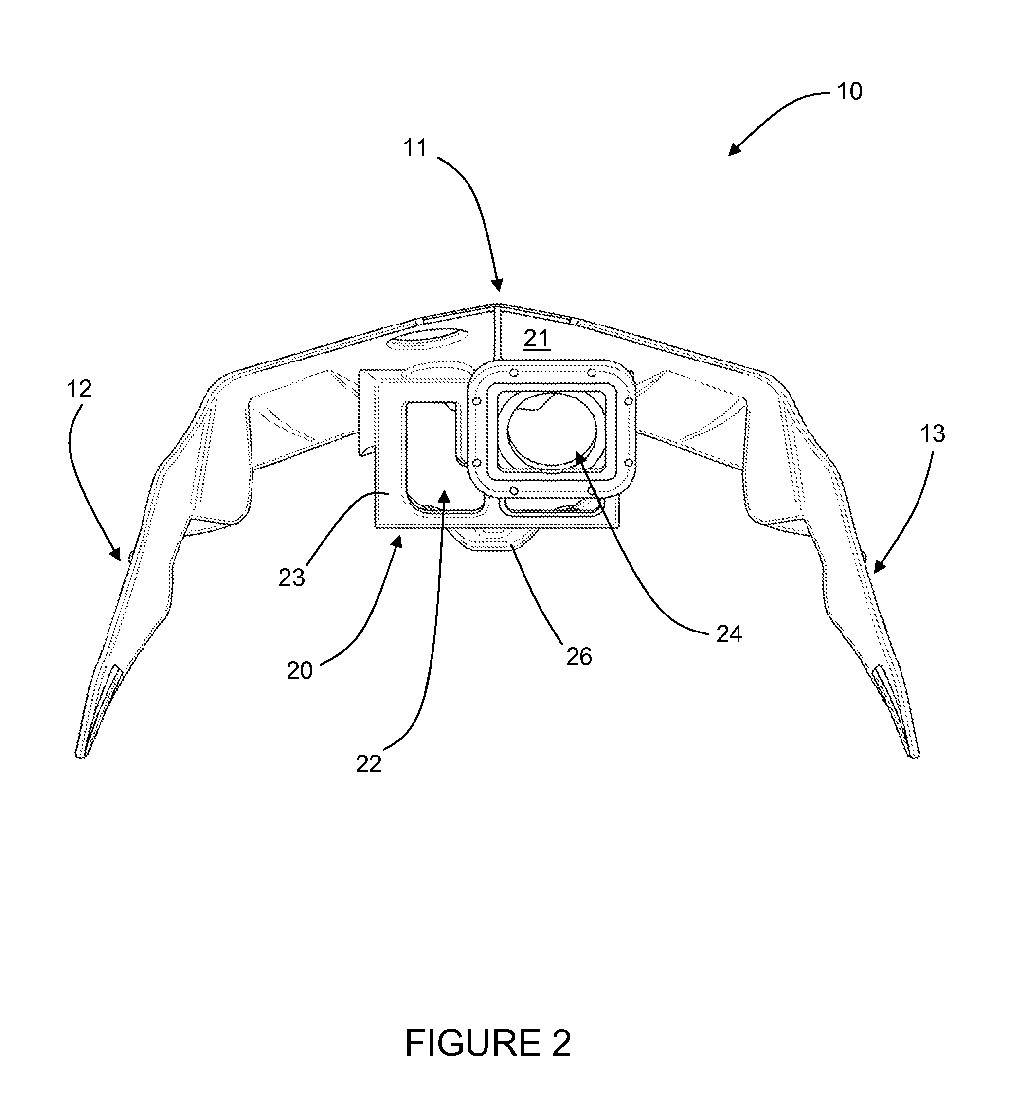
[0034]Referring to the drawings, an exemplary visor constructed according to the present invention is illustrated in FIGS. 1-7 and shown generally at reference numeral 10. As shown, the visor 10 is adapted for attachment to an existing support structure or head gear such as a helmet; however, it should be appreciated that the visor 10 may be attached to or integrally formed with any suitable support structure where a visor would be used, such as the aforementioned helmet or a baseball cap.

[0035]The visor 10 includes an upper portion 11, a left side portion 12 extending downwardly from a left side of the upper portion 11, and a right side portion 13 extending downwardly from the right side of the upper portion 11. The left and right side portions 12, 13 each include at least one slot 14 and 16, respectively, for receiving a fastener therethrough to secure the visor 10 to a helmet.

[0036]A camera mount 20 is connected to an underside 21 of the upper portion 11. The camera mount 20 is d...


PUM


Abstract

A visor is disclosed. The visor includes an upper portion, a left side portion extending downwardly from a left side of the upper portion, a right side portion extending downwardly from a right side of the upper portion, and a camera mount configured to secure a camera to the visor. The camera mount is connected to an underside of the upper portion to prevent damage of a camera secured therein.

Description

BACKGROUND OF THE INVENTION[0001]The present invention relates generally to a visor, and more particularly to a visor having an integrated camera mount and / or lights.[0002]In the past, cameras were primarily used for photography, home movies, or to film television shows and movies. However, with the advent of digital and computer technologies, cameras have become a mainstay in society. Today, cameras have become a standard feature on cell phones and computers for use in social media and to allow users to record their daily activity, if so desired.[0003]One area where cameras are being utilized to their fullest is in sports. Television networks are now using multiple cameras positioned around a sporting venue, cameras on wires to traverse a field, and cameras on helmets, racecars, motorcycles, etc. to provide viewers with different angles of view and a more realistic experience.[0004]One such sport where these cameras are being utilized is in sports such as motocross or sports contai...

Claims


Application Information

Patent Timeline
Patent Type & Authority Applications(United States)
IPC IPC(8): A42B3/04A42B3/22
CPCA42B3/22A42B3/044A42B3/042A42B3/227
Inventor O'DELL, NICK
Owner ODELL NICK
Learn More