Vehicle battery mounting structure

a technology for mounting structures and battery frames, applied in the direction of vehicle sub-unit features, cell components, vehicle sub-unit details, etc., can solve the problems of damage to the fixing portions of the battery frame to the under members, and achieve the effect of increasing the surface rigidity of the fastening portion

Active Publication Date: 2015-06-25
TOYOTA JIDOSHA KK
View PDF33 Cites 42 Cited by
  • Summary
  • Abstract
  • Description
  • Claims
  • Application Information

AI Technical Summary

Benefits of technology

[0016]According to the above configuration, the vehicle width direction outside end portion of the curved or bent shape of the ridge line of the fastening portion is formed further to the vehicle width direction inside than a hypothetical straight line running in the vehicle front-rear direction to pass through the center of the hole in plan view. Surface rigidity of the fastening portion is accordingly increased, and collision load input to the flange through the fastener in the event of a side collision of the vehicle is even more efficiently distributed in the vehicle front-rear direction along the ridge lines. Accordingly, in the event of a side collision of the vehicle, damage to the flange that is a location on the resin battery frame side for fixing to the floor side is further suppressed or prevented.

Problems solved by technology

However, in resin battery frames, there is a concern of damage to fixing portions of the battery frame to the under members (floor side) due to collision load input when the vehicle experiences a side collision.

Method used


Image

  • Vehicle battery mounting structure
  • Vehicle battery mounting structure
  • Vehicle battery mounting structure

Examples


Embodiment Construction

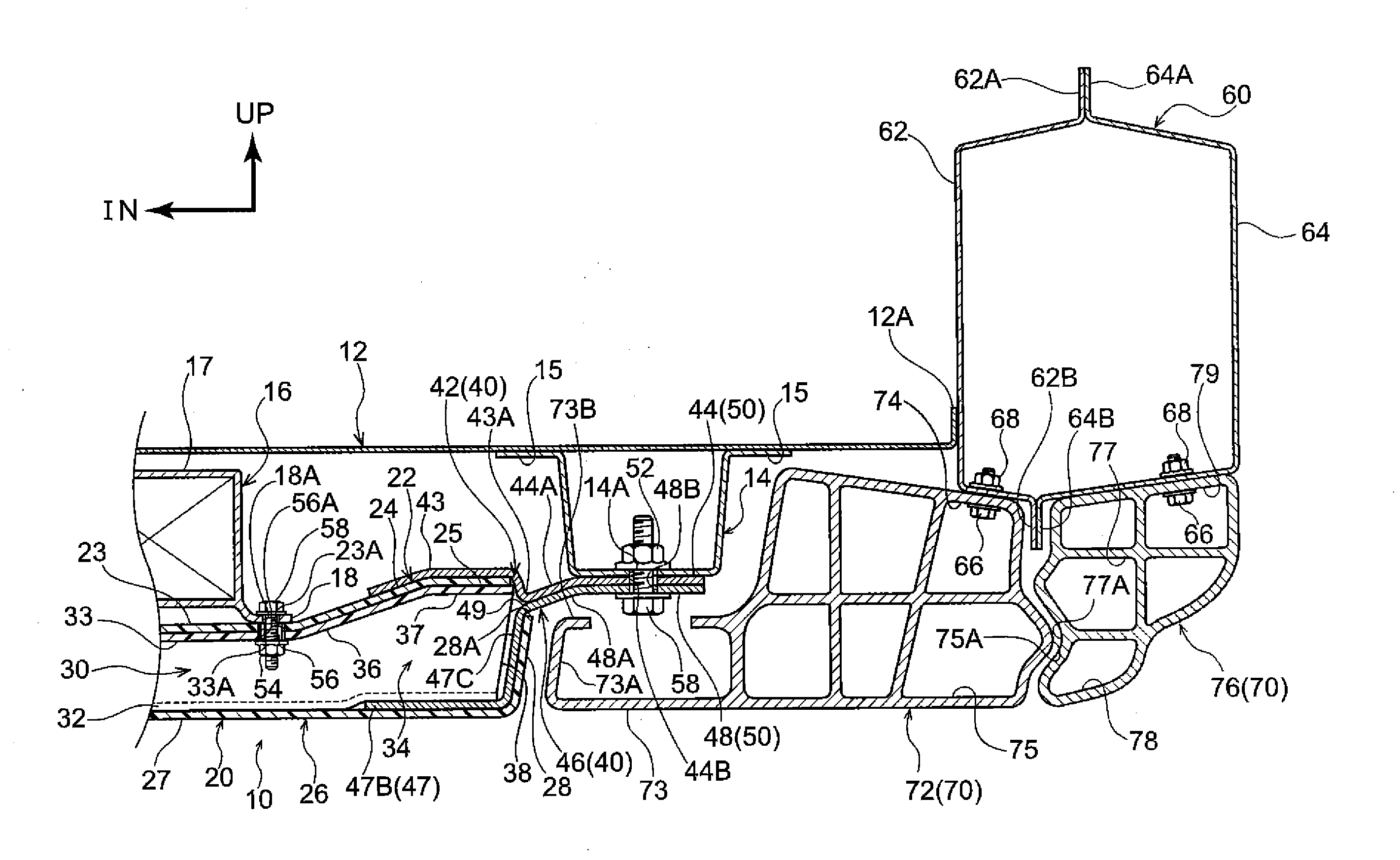
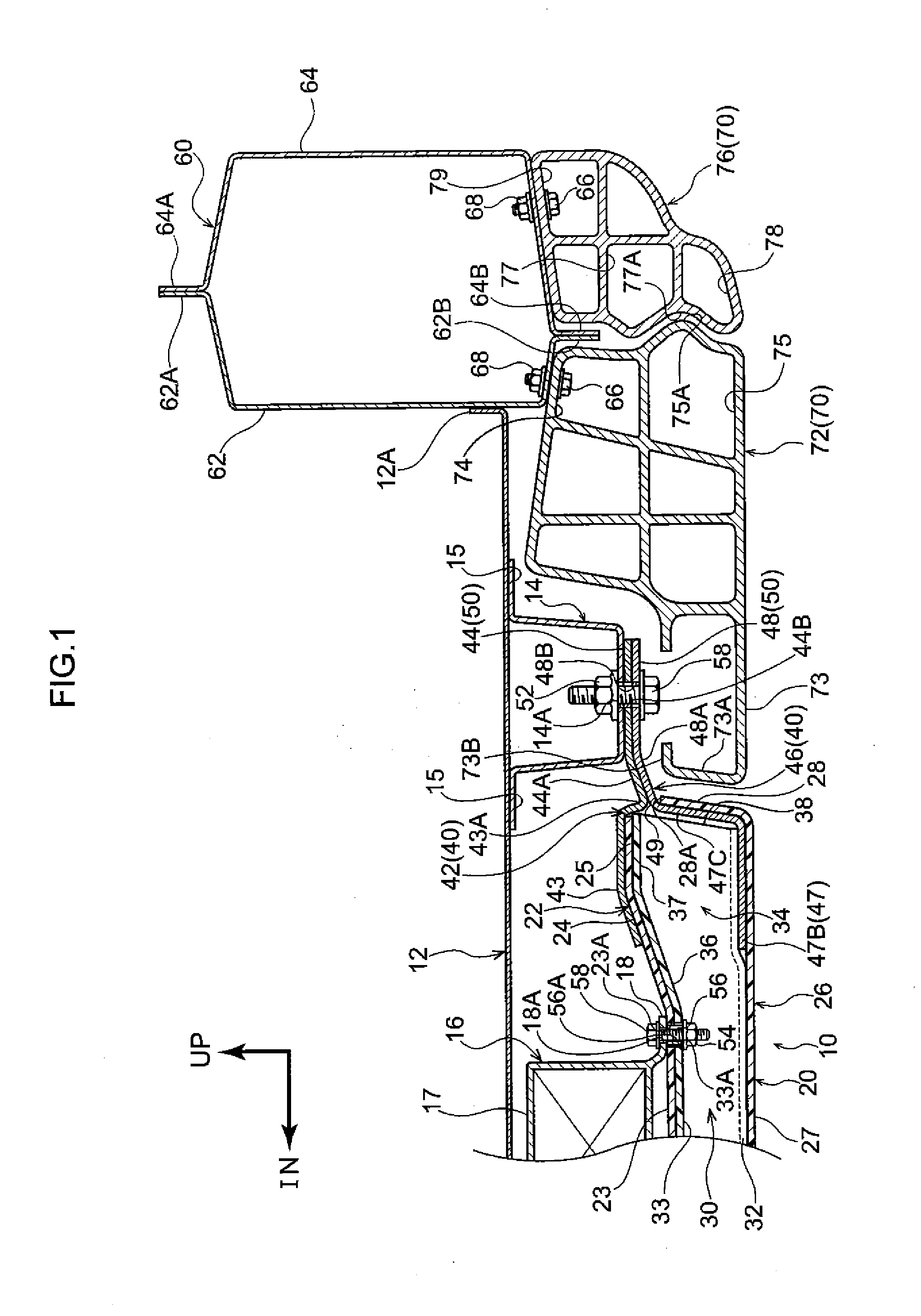
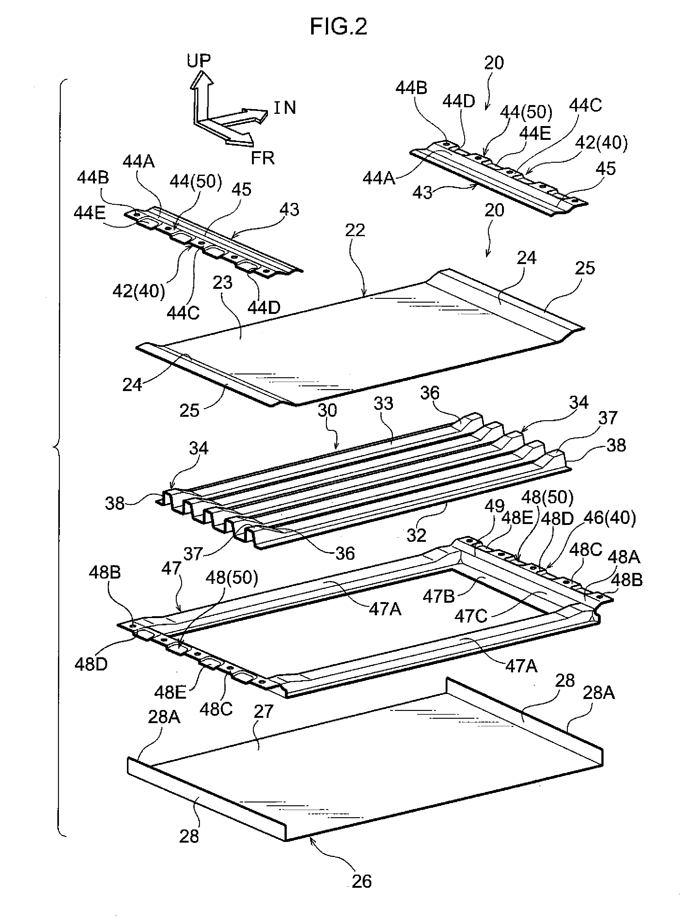
[0025]Detailed explanation follows regarding an exemplary embodiment, with reference to the drawings. To aid explanation, in each of the drawings, the arrow UP indicates the vehicle upward direction, the arrow FR indicates the vehicle front direction, and the arrow IN indicates the vehicle width direction inside. Unless specifically indicated otherwise, where employed in the following explanation, the up and down, front and rear, and left and right directions indicate up and down in the vehicle up-down direction, front and rear in the vehicle front-rear direction, and left and right in the vehicle left-right direction (vehicle width direction). The left side of a vehicle body is illustrated in each of the drawings; however, since the right side of the vehicle body is configured similarly but with left-right symmetry, explanation regarding the right side of the vehicle body is omitted.

[0026]As illustrated in FIG. 1, a pair of left and right under members (side frames) 14, included in...


PUM

PropertyMeasurementUnit
widthaaaaaaaaaa
ductileaaaaaaaaaa
lengthaaaaaaaaaa

Abstract

A vehicle battery mounting structure includes a battery frame that is disposed at a vehicle lower side of a floor panel, and is made from resin; a ductile member that includes a main body joined to the battery frame and a flange contiguously formed at a vehicle width direction outside end of the main body, the flange having a hole, and the ductile member being fastened to a lower face of the floor panel using a fastener inserted through the hole; and a fastening portion that is formed in a region including the hole, having a substantially hat shaped cross-section profile projecting toward a vehicle upper side and having ridge lines on vehicle front-rear direction sides of the region, and the ridge lines being formed with curved or bent shape toward directions heading away from the hole on progression toward a vehicle width direction inside in plan view.

Description

CROSS-REFERENCE TO RELATED APPLICATION[0001]This application is based on and claims priority under 35 USC 119 from Japanese Patent Application No. 2013-267962 filed on Dec. 25, 2013, the disclosure of which is incorporated by reference herein.BACKGROUND[0002]1. Technical Field[0003]The present invention relates to a vehicle battery mounting structure.[0004]2. Related Art[0005]A structure has been known in which battery frames for housing a drive battery that is disposed below the floor of an electric vehicle are formed from fiber reinforced plastic (FRP), and are fixed to side frames (under members) disposed on the left and right at a lower face of the floor (see, for example, Japanese Patent No. 4924684).[0006]However, in resin battery frames, there is a concern of damage to fixing portions of the battery frame to the under members (floor side) due to collision load input when the vehicle experiences a side collision. There is accordingly a room for improvement in structures to pre...

Claims


Application Information

Patent Timeline
Patent Type & Authority Applications(United States)
IPC IPC(8): B60K1/04H01M50/224H01M50/227H01M50/249
CPCB60K2001/0438B60K1/04H01M8/2465H01M16/003B60Y2306/01H01M2250/20Y02T90/40Y02E60/50Y02E60/10H01M50/227H01M50/249H01M50/224
Inventor IKEDA, KOKIHOKAZONO, KIYOSHIKAMIMURA, SHINYANAKAMURA, KENTARO
Owner TOYOTA JIDOSHA KK
Why Eureka
Try Eureka