Method and system for multi-phase flow measurement

a multi-phase flow and measurement method technology, applied in the direction of liquid/fluent solid measurement, instruments, heat measurement, etc., can solve the problems of inability to use real-time control, difficult or costly to obtain reliable measurements, and only limited information about multi-phase flow

Active Publication Date: 2015-06-25
EXXON RES & ENG CO
View PDF4 Cites 32 Cited by
  • Summary
  • Abstract
  • Description
  • Claims
  • Application Information

AI Technical Summary

Benefits of technology

[0014]In certain embodiment, the second sensing cable further includes a passive fiber optic sensor array having a plurality passive sensors and the method can include measuring, over time, a temperature profile of the second sensing cable each of the plurality of passive sensors corresponding to the heat pulse. The method can include determining a flow velocity of the one or more media flowing through the component at each of the plurality of active sensors by correlating the temperature profile of each of the active sensors with the temperature profile of at least a respective one of the passive sensors. Detecting the condition of flow can further include detecting a volumetric and mass flow rate of each phase of the instantaneous phase fraction of the one or more media based upon the determined flow velocity at each of the plurality of active sensors, the determined phase of the at least one medium at each of the plurality of active sensors, and the location of each of the plurality of active sensors within the component.
[0015]In accordance with another aspect of the disclosed subject matter a system for detecting a condition of multi-phase flow through a component having one or more media flowing therethrough includes a first sensing cable aligned with a heating element and including at least one active optical fiber sensor at a first sensing location within a component and at least a second sensing cable including at least one optical fiber sensor at a second sensing location, the second sensing location being at a predetermined distance from the first sensing location. The system includes an excitation source configured to propagate at least one heat pulse through the heating element along at least a portion of the first sensing cable to affect an exchange of thermal energy between the heating element and at least one medium exposed to the sensing cable. The system includes an optical signal interrogator coupled with the first sensing cable and the second sensing cable, to measure, over time, a first temperature profile of the first sensing cable at the first sensing location corresponding to the heat pulse, and a second temperature profile of the second sensing cable at the second sensing location corresponding to the heat pulse. The system includes a control unit, coupled to the optical signal interrogator, to determine a flow velocity of the one or more media flowing through the component by correlating the first temperature profile with the second temperature profile; and configured to detect a condition of flow of the one or more media by determining a phase of the at least one medium exposed to the sensing cable at the first sensing location based on the first temperature profile and the determined flow velocity.
[0016]In certain embodiments, the first sensing cable can include an active fiber optic sensor array having a plurality of active sensors, each active sensor having a location within the component and the optical signal interrogator can be configured to measure, over time, a temperature profile of the first sensing cable at each of the plurality of active sensors corresponding to the heat pulse. The control unit can be configured to detect the condition of flow further by determining the phase of the at least one medium exposed to the sensing cable at each of the plurality of active sensors based on the corresponding temperature profile and the determined flow velocity. The plurality of active sensors can be arranged circumferentially along a perimeter of a wall of the component. Additionally or alternatively, the plurality of active sensors can be arranged in a grid pattern over a cross section of the component.
[0017]As embodied herein, the control unit can be configured to detect the condition of flow by detecting an instantaneous phase fraction based upon the determined phase of the at least one medium at each of the plurality of active sensors and the location of each of the plurality of active sensors within the component. Additionally or alternatively, the control unit can be configured to detect the condition of flow by detecting flow regime based upon the determined phase of the at least one medium at each of the plurality of active sensors over time and the location of each of the plurality of active sensors within the component.
[0018]In certain embodiments, the second sensing cable can include a passive fiber optic sensor array having a plurality passive sensors. The optical signal interrogator can be configured to measure, over time, a temperature profile of the second sensing cable each of the plurality of passive sensors corresponding to the heat pulse and the control unit can be configured to determine a flow velocity of the one or more media flowing through the component at each of the plurality of active sensors by correlating the temperature profile of at least a respective one of the active sensors with the temperature profile of each of the passive sensors. The control unit can be further configured to detect the condition of flow by detecting a volumetric and mass flow rate of each phase of the instantaneous phase fraction of the one or more media based upon the determined flow velocity at each of the plurality of active sensors, the determined phase of the at least one medium at each of the plurality of active sensors, and the location of each of the plurality of active sensors within the component.

Problems solved by technology

However, such components can involve harsh conditions, such as high temperature, high pressure, and / or a corrosive environment, making it difficult or costly to obtain reliable measurements.
A separator, however, can be bulky and measurement typically must be accomplished offline and thus cannot be used for real time control.
Such techniques, however, provide only limited information about multi-phase flow.
For example, nuclear magnetic resonance imaging techniques can be used to image the flow in a small pipes, but cannot be used for lager pipes.
Other radiation-based approaches, such as X-ray and gamma-ray imaging and electrical tomography can achieve only limited resolution and can be inadequate for many application.

Method used


Image

  • Method and system for multi-phase flow measurement
  • Method and system for multi-phase flow measurement
  • Method and system for multi-phase flow measurement

Examples


embodiment 1

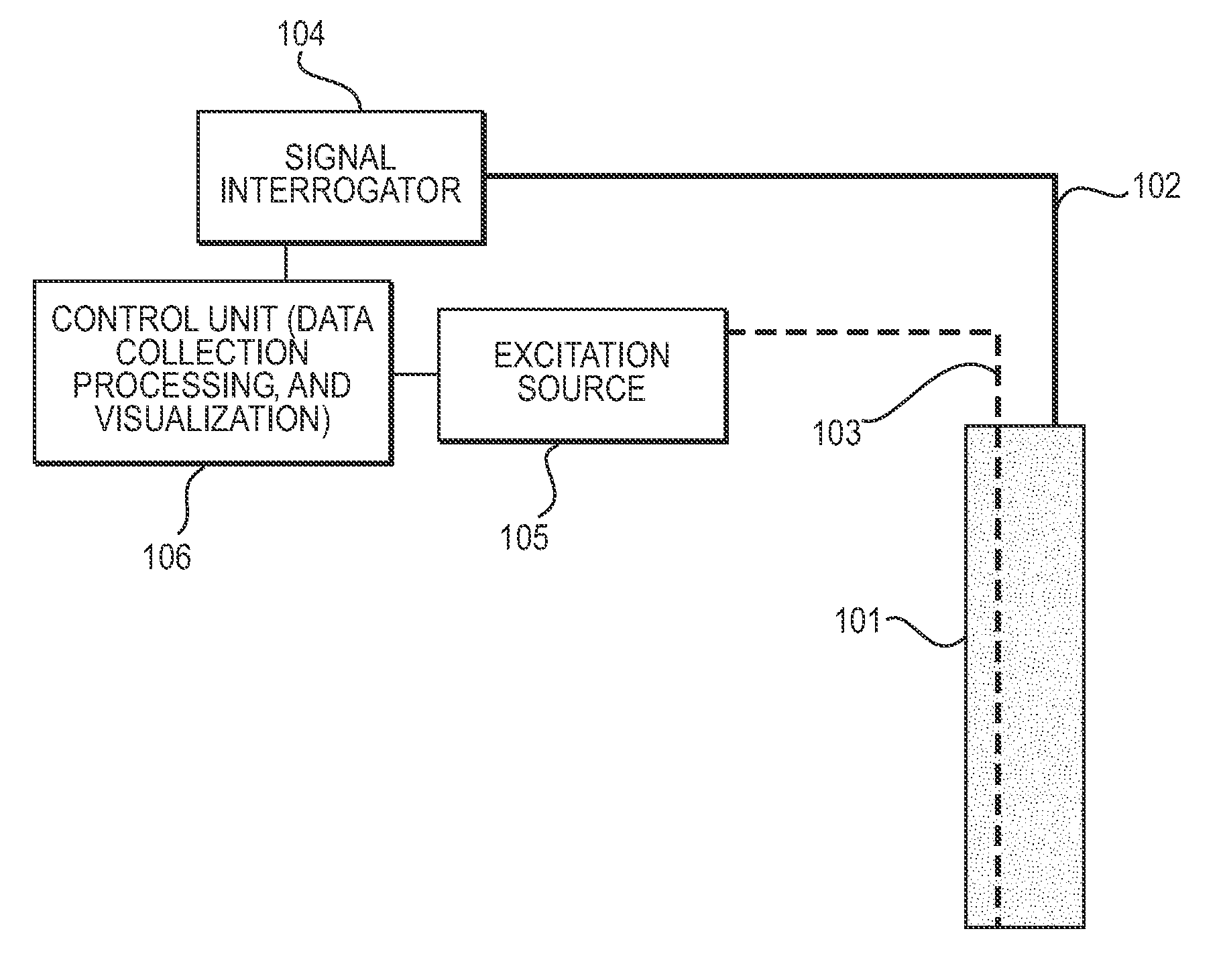
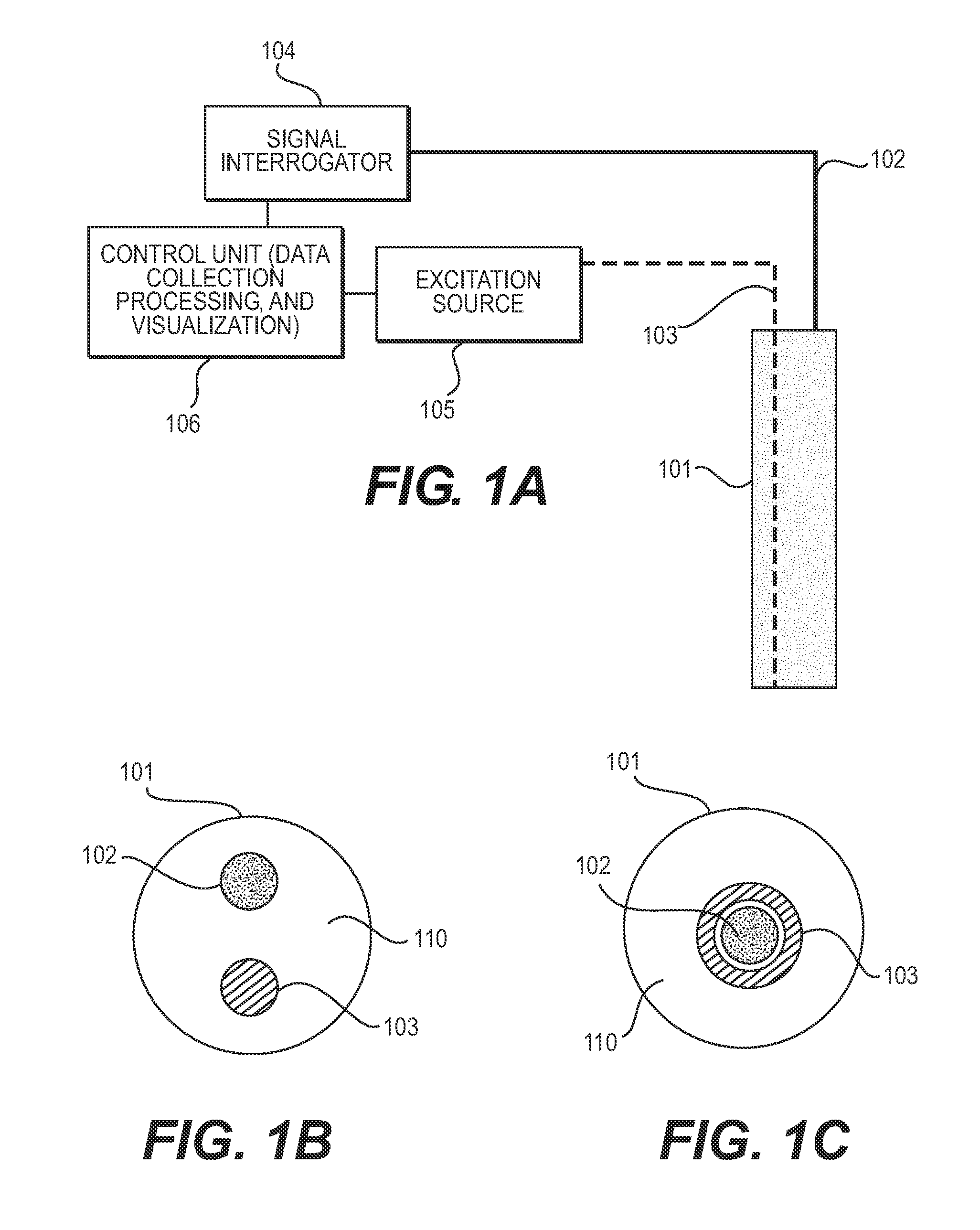
[0115]a method for detecting a condition of multi-phase flow through a component having one or more media flowing therethrough, comprising: providing within a component a first sensing cable aligned with a heating element and including at least one active optical fiber sensor at a first sensing location; providing within the component at least a second sensing cable including at least one optical fiber sensor at a second sensing location, the second sensing location being at a predetermined distance from the first sensing location; propagating at least one heat pulse through the heating element along at least a portion of the first sensing cable to affect an exchange of thermal energy between the heating element and at least one medium exposed to the sensing cable; measuring, over time, a first temperature profile of the first sensing cable at the first sensing location corresponding to the heat pulse; measuring, over time, a second temperature profile of the second sensing cable at...

embodiment 2

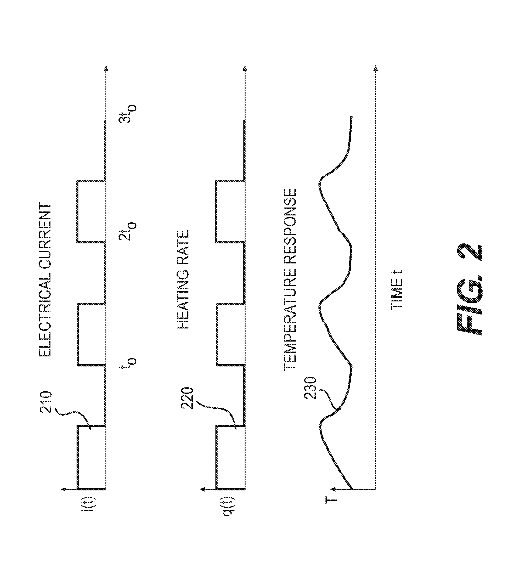
[0116]the method of any of the previous embodiments, wherein measuring the temperature profile corresponding to the heat pulse at the first sensing location includes measuring at least a heating temperature measurement during propagation of the heat pulse over the sensor location, a peak temperature measurement, and a cooling temperature measurement after propagation of the heat pulse over the sensor.

embodiment 3

[0117]the method of any of the previous embodiments, wherein measuring the temperature profile corresponding to the heat pulse at the first sensing location includes measuring a plurality of temperatures over a period of time upon arrival of the heat pulse at the sensor location.


PUM

PropertyMeasurementUnit
lengthaaaaaaaaaa
response timeaaaaaaaaaa
frequencyaaaaaaaaaa

Abstract

Systems and methods for detecting a condition of multi-phase flow through a component with a first sensing cable having a first sensor location and aligned with a heating element and a second sensing cable having a second sensing location a predetermined distance from the first sensing location. A heat pulse is propagated through the heating element. A first temperature profile at the first sensing location and a second temperature profile at the second sensing location, each corresponding to the heat pulse, are measured over time. A flow velocity is determined by correlating the first temperature profile with the second temperature profile. A condition of flow of the media is detected by determining a phase of at least one medium exposed to the sensing cable at the first sensing location based on the first temperature profile and the determined flow velocity.

Description

CROSS REFERENCE TO RELATED APPLICATIONS[0001]This application relates and claims priority to U.S. Provisional Patent Application No. 61 / 919,870, filed on Dec. 23, 2013.BACKGROUND[0002]1. Field[0003]The presently disclosed subject matter relates to methods and systems for determining the flow distribution of a fluid through a component. More particularly, the presently disclosed subject matter relates to measuring multi-phase flow in a pipe.[0004]2. Description of Related Art[0005]Components of certain equipment, such as that used in the petroleum and petrochemical industry, which includes the exploration, production, refining, manufacture, supply, transport, formulation or blending of petroleum, petrochemicals, or the direct compounds thereof, are often monitored to maintain reliable operation. However, such components can involve harsh conditions, such as high temperature, high pressure, and / or a corrosive environment, making it difficult or costly to obtain reliable measurements.[...

Claims


Application Information

Patent Timeline
Patent Type & Authority Applications(United States)
IPC IPC(8): G01F1/74G01K11/32G01F1/68
CPCG01F1/74G01K11/32G01F1/68E21B47/07E21B47/135G01F1/662G01F1/684G01F1/7044G01K11/3206
Inventor SONG, LIMINZHANG, YIBING
Owner EXXON RES & ENG CO
Why Eureka
Try Eureka