Control system and method for energy smart fan

a technology of control system and fan, applied in adaptive control, program control, instruments, etc., can solve the problems of large energy consumption, burden on people's daily life, and increase in energy source price, and achieve the effect of saving energy and comforting indoor temperatur

Inactive Publication Date: 2015-06-25
LO CHEN MEI
View PDF4 Cites 11 Cited by
  • Summary
  • Abstract
  • Description
  • Claims
  • Application Information

AI Technical Summary

Benefits of technology

[0007]The object of the invention is to provide a control system and method for an energy smart fan. A rotational speed of a fan is regulated according to comparison of a PMV value of an internal space in which an air conditioner and the fan is mounted with a preset PMV index range to have a comfortable indoor temperature and save energy.
[0008]The invention provides a control system and method for an energy smart fan. The control method in accordance with an exemplary embodiment of the invention includes pre-setting a PMV index range for a internal space in which a fan and an air conditioner is mounted and measuring a PMV value of the internal space; comparing the PMV value of the internal space with the PMV index range; and increasing a rotational speed of the fan when the PMV value of the internal space is greater than the PMV value of the PMV index region, and decreasing the rotational speed of the fan when the PMV value of the internal space is less than the PMV value of the PMV index region.

Problems solved by technology

Because the price of energy source increases, the cost of energy consumption for air conditioner becomes a burden for people's daily life.
For example, a ceiling fan is often used in an office to provide air flows which reduces the energy consumption of an air conditioning system because utilization of a single air conditioning system may cause large energy consumption.
However, the fan devices for air conditioning system are usually regulated manually, which causes over heated or over cooled environment.
Therefore, the energy consumption increases, and the over-heated or over-cooled environment makes people uncomfortable.

Method used


Image

  • Control system and method for energy smart fan
  • Control system and method for energy smart fan
  • Control system and method for energy smart fan

Examples


Embodiment Construction

[0020]The following description is of the best-contemplated mode of carrying out the invention. This description is made for the purpose of illustrating the general principles of the invention and should not be taken in a limiting sense. The scope of the invention is best determined by reference to the appended claims.

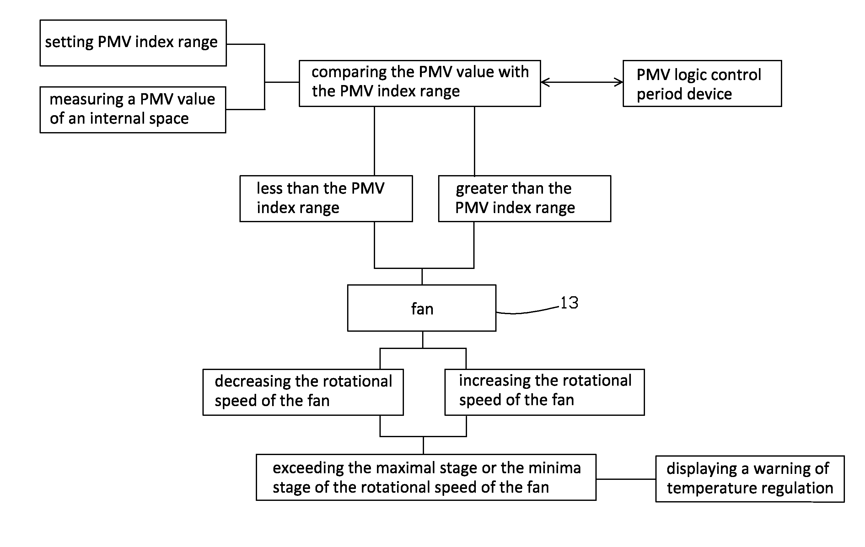
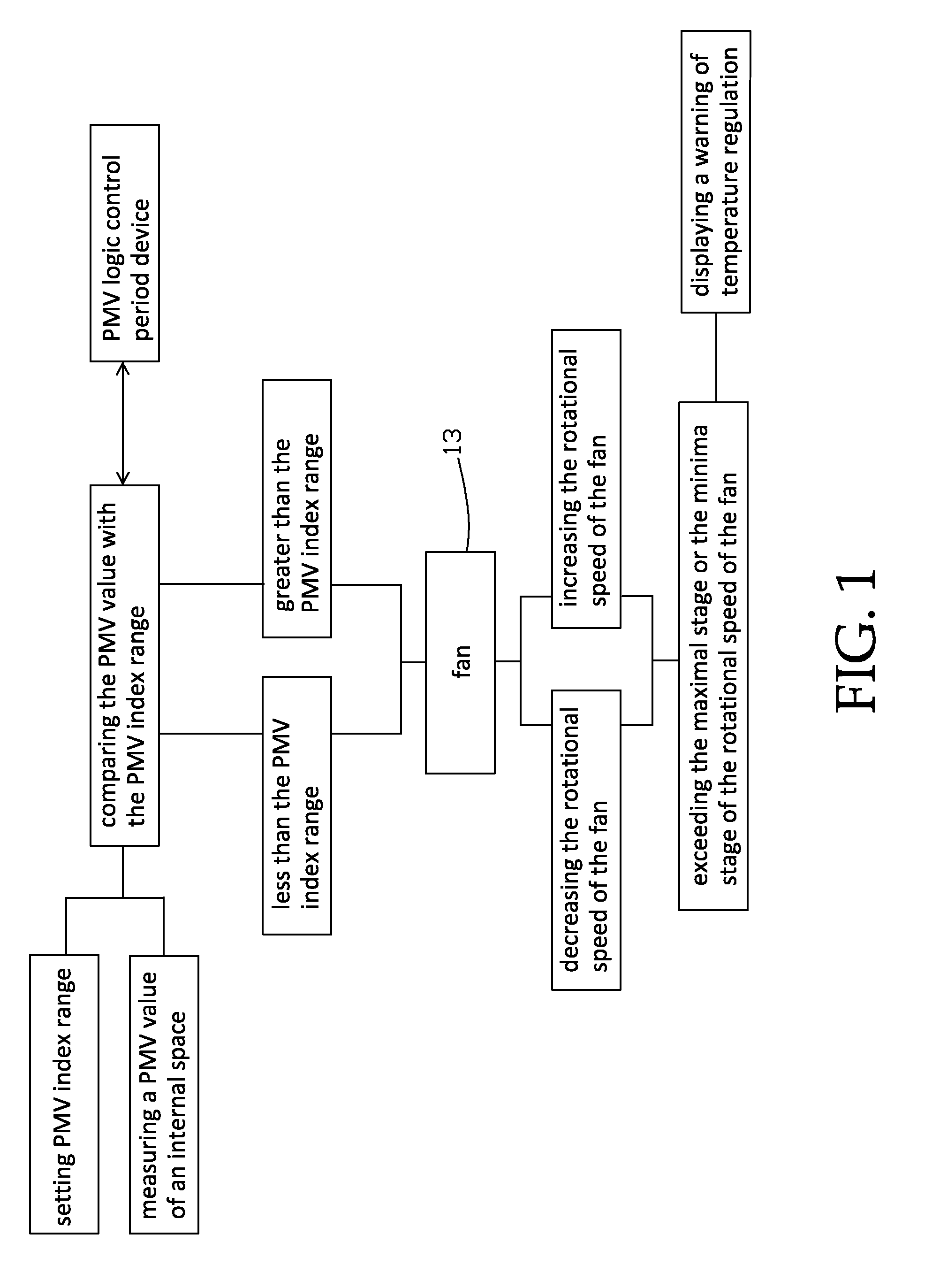
[0021]Human's thermo-comfortability depend on six factors, temperature, air humidity, average radiation temperature, human activity content and cloth content. A predicted mean value (PMV) index estimating the human's thermo-comfortability is obtained according to the six factors. The PMV index ranges from −3 (the coldest) to +3 (the hottest), and the PMV index 0 means moderate. The PMV index is obtained by the following equation:

PMV=[0.303exp(-0.036M)+0.028]×{(M-W)-3.05[5.73-0.007(M-W)-Pa]-0.42[(M-W)-58.15]-0.0173M(5.87-Pa)+0.0014M(34-ta)-3.96-8×fcl×[(tcl+273)4-(MRT+273)4]-fcl×hc×(tcl-ta)}

wherein exp=2.718281828, M: metabolic rates (W / m2), W: working rate (W / m2), Icl: ...


PUM


Abstract

A control method includes pre-setting a PMV index range for an internal space in which a fan and an air conditioner is mounted and measuring a PMV value of the internal space; comparing the PMV value of the internal space with the PMV index range; and increasing a rotational speed of the fan when the PMV value of the internal space is greater than the PMV value of the PMV index region, and decreasing the rotational speed of the fan when the PMV value of the internal space is less than the PMV value of the PMV index region.

Description

BACKGROUND OF THE INVENTION[0001]1. Field of the Invention[0002]The invention relates to a control system and method for an energy smart fan, and more particularly to a control system and method for an energy smart fan comparing a PMV index of an internal space with a preset PMV index range to determine a rotational speed of the fan.[0003]2. Description of the Related Art[0004]Air conditioners are used to provide a comfortable environment, such as cooling a high temperature environment or heating a low temperature environment. Most conventional air conditioners can provide cool air and heat air to regulate a temperature of an internal space. Because the price of energy source increases, the cost of energy consumption for air conditioner becomes a burden for people's daily life.[0005]It is very often to utilize other devices to reduce energy consumption of air conditioner. For example, a ceiling fan is often used in an office to provide air flows which reduces the energy consumption ...

Claims


Application Information

Patent Timeline
Patent Type & Authority Applications(United States)
IPC IPC(8): G05D23/19G05B15/02
CPCG05B15/02G05D23/1917G05B2219/2614G05B2219/2642F24F11/46F24F11/77Y02B30/70
Inventor YEH, TIEN-BAO
Owner LO CHEN MEI
Why Eureka
Try Eureka