Eureka AIR delivers breakthrough ideas for toughest innovation challenges, trusted by R&D personnel around the world.

Separator enclosures for electrodes and electrochemical cells

a technology of electrochemical cells and separater enclosures, which is applied in the field of electrochemical storage and conversion devices, can solve the problems of dendrite formation and practicability, and achieve the effect of improving the cell performan

Active Publication Date: 2015-06-25
CALIFORNIA INST OF TECH
View PDF4 Cites 77 Cited by
  • Summary
  • Abstract
  • Description
  • Claims
  • Application Information

AI Technical Summary

Benefits of technology

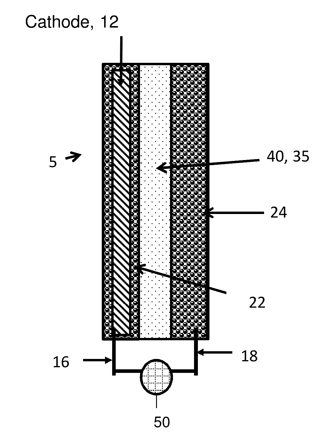
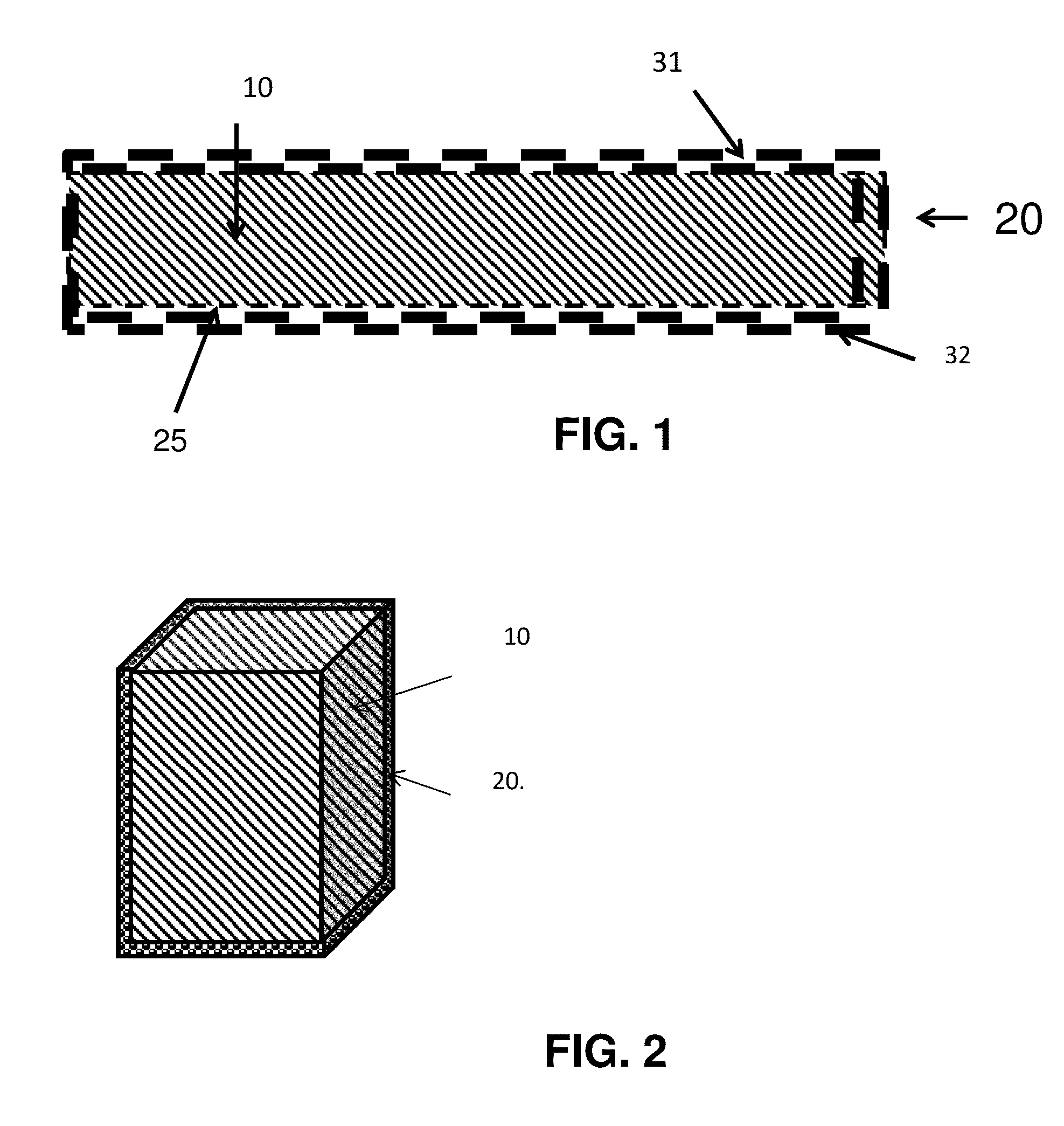
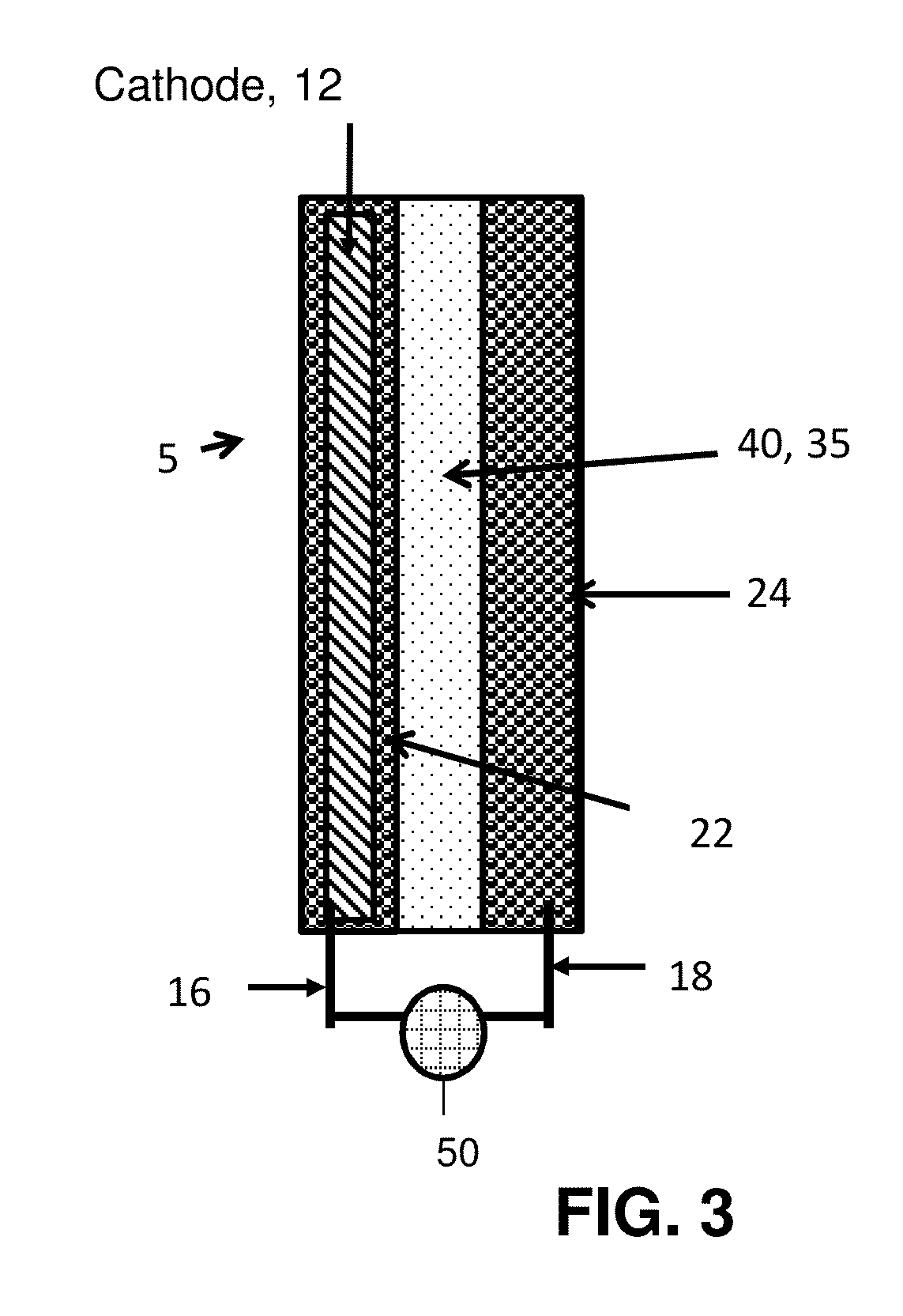
[0008]In one aspect, the disclosure provides electrochemical cells including a separator enclosure which encloses at least a portion of a positive or negative electrode. In an embodiment, the separator generates a contact force or pressure on the entire free surface, or a portion thereof, of the electrode which can improve the performance of the cell. Advantages provided by some embodiments of the invention are achieved by the internal application of a contact force or pressure on one or more electrodes, as opposed to an external application of a contact force or pressure.
[0009]The applied pressure can improve the cycle life, e.g., by maintaining sufficient contact between the cell components. For example, the applied pressure is very helpful in cycling metal based electrodes such as lithium metal, zinc metal, ZnO or silicon anode. The applied pressure is also helpful to prevent material loss of the electrode and can help with the uniformity of the electrode, for example, by providing a substantially uniform thickness along the length of the electrode (e.g., deviations from an average thickness less than or equal to 20% and optionally less than or equal to 10% and optionally less than or equal to 5%). One example is in batteries such as lead acid batteries, lithium batteries or alkaline batteries (e.g. Zinc batteries), where the applied pressure can hinder the shape change of the electrode and thus improve the performance and cycle life. The applied pressure by the separator bag can also result in uniform and smooth electrode surfaces during cycling. Another benefit of the separator bag invention is the reduction in the required binder in the electrode, which itself results in higher percentage of active materials and thus higher energy and power density at a lower cost. Note that in electrode designs wherein the dominant contact between electrode media and current collector is through a facial area (e.g. a flat foil); a common performance decay mechanism is delamination which results in at least partial increase in electronic resistivity. Some embodiments of the invention incorporate a separator enclosure comprising a separator bag or container to mitigate this and related effects.

Problems solved by technology

Despite substantial advances, practical challenges remain in connection with the continued development of metal based electrochemical systems such as lithium, zinc, magnesium, sodium, iron or aluminum based electrochemical systems.
A significant issue, for example, relates to dendrite formation in primary and secondary lithium and lithium ion batteries.
It is generally known that Li deposition in many electrolytes is highly dendritic which make these systems susceptible to problems involving shorting, mechanical failure and thermal runaway.
Safety concerns relating to dendrite formation are currently a barrier to implementation of metal Li anodes in rechargeable systems.

Method used


Image

  • Separator enclosures for electrodes and electrochemical cells
  • Separator enclosures for electrodes and electrochemical cells
  • Separator enclosures for electrodes and electrochemical cells

Examples


example 1

Electrode Confinement in a Separator Cloth

[0103]A novel separator for electrochemical cells is introduced. An example is such that the separator covers at least the entire surface of an electrode facing the opposite electrode. In some embodiments the separator can have a closed geometry such that it can cover all the surfaces of an electrode. In some embodiments the separators can apply pressure on at least one surface of an electrode. The applied pressure can improve the performance of the cell such as cycle life, e.g., by maintaining sufficient contact between the cell components. For example, the applied pressure is very helpful in cycling metal based electrodes such as lithium metal, zinc metal, ZnO or silicon anode. The applied pressure is also helpful to prevent material loss of the electrode, for example the applied pressure can help with the uniformity of the electrode, such as providing an electrode having a substantially uniform thickness (e.g., deviations from an average ...

example 2

Separators for Electrodes and Electrochemical Cells

[0118]A novel separator for electrochemical cells is introduced such that the separator covers the entire surface of an electrode facing the opposite electrode In some embodiments the separators cab apply pressure on at least one electrode. The applied pressure can improve the performance of the cell such as cycle life. For example, the applied pressure is very helpful in cycling metal based electrodes such as lithium metal and zinc metal. The applied pressure is also helpful to prevent material loss of the electrode, for example the applied pressure can help with the uniformity of the electrode. One example can be in batteries such as lead acid batteries or lithium batteries or alkaline batteries (e.g. Zinc batteries) that the applied pressure can hinder the shape change of the electrode and thus improves the performance and cycle life. The applied pressure by the separator can result in uniform and smooth electrode surfaces during...


PUM

PropertyMeasurementUnit
porosityaaaaaaaaaa
porosityaaaaaaaaaa
contact pressureaaaaaaaaaa

Abstract

The disclosure provides electrochemical cells including a separator enclosure which encloses at least a portion of a positive or negative electrode. In an embodiment, the separator generates a contact force or pressure on at least a portion of the electrode which can improve the performance of the cell. The disclosure also provides methods for charging an electrochemical cell.

Description

CROSS-REFERENCE TO RELATED APPLICATIONS[0001]This application claims the benefit of and priority to U.S. Provisional Application No. 61 / 905,678, filed Nov. 18, 2013; U.S. Provisional Application No. 61 / 938,794, filed Feb. 12, 2014; U.S. Provisional Application No. 61 / 985,204, filed Apr. 28, 2014; and U.S. Provisional Application No. 62 / 024,104, filed Jul. 14, 2014; all of which are hereby incorporated by reference in their entireties to the extent not inconsistent herewith.BACKGROUND OF INVENTION[0002]Over the last few decades revolutionary advances have been made in electrochemical storage and conversion devices expanding the capabilities of these systems in a variety of fields including portable electronic devices, air and space craft technologies, passenger vehicles and biomedical instrumentation. Current state of the art electrochemical storage and conversion devices have designs and performance attributes that are specifically engineered to provide compatibility with a diverse ...

Claims


Application Information

Patent Timeline
Patent Type & Authority Applications(United States)
IPC IPC(8): H01M2/16H01M50/457H01M50/489H01M50/491H01M50/494H01M50/497
CPCH01M2/1673H01M10/052H01M10/4235H01M10/48Y02E60/10H01M50/497H01M50/491H01M50/489H01M50/457H01M50/494G01R31/3828G01R31/3835G01R31/3842H01M50/46H01M10/4257
Inventor ROUMI, FARSHID
Owner CALIFORNIA INST OF TECH
Why Eureka
Eureka Blog
Learn More