Polymer electrolyte film and method for preparation of the same, and solid polymer type fuel cell using the same

a technology of polymer electrolyte and polymer film, which is applied in the field of polymer electrolyte membrane (pem), can solve the problems of lowering the cellular output power and energy efficiency

Inactive Publication Date: 2005-04-07
TORAY IND INC
View PDF5 Cites 73 Cited by
  • Summary
  • Abstract
  • Description
  • Claims
  • Application Information

AI Technical Summary

Problems solved by technology

As mentioned above, DMFC has a problem of crossover as fuel methanol perme

Method used


Image

  • Polymer electrolyte film and method for preparation of the same, and solid polymer type fuel cell using the same
  • Polymer electrolyte film and method for preparation of the same, and solid polymer type fuel cell using the same
  • Polymer electrolyte film and method for preparation of the same, and solid polymer type fuel cell using the same

Examples


example 1

[0100] (1) Preparation of Multipore Film

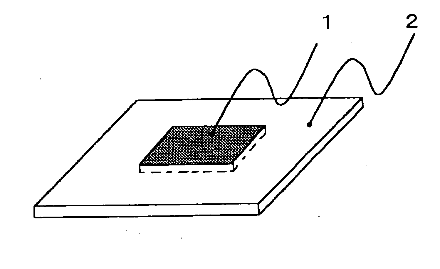
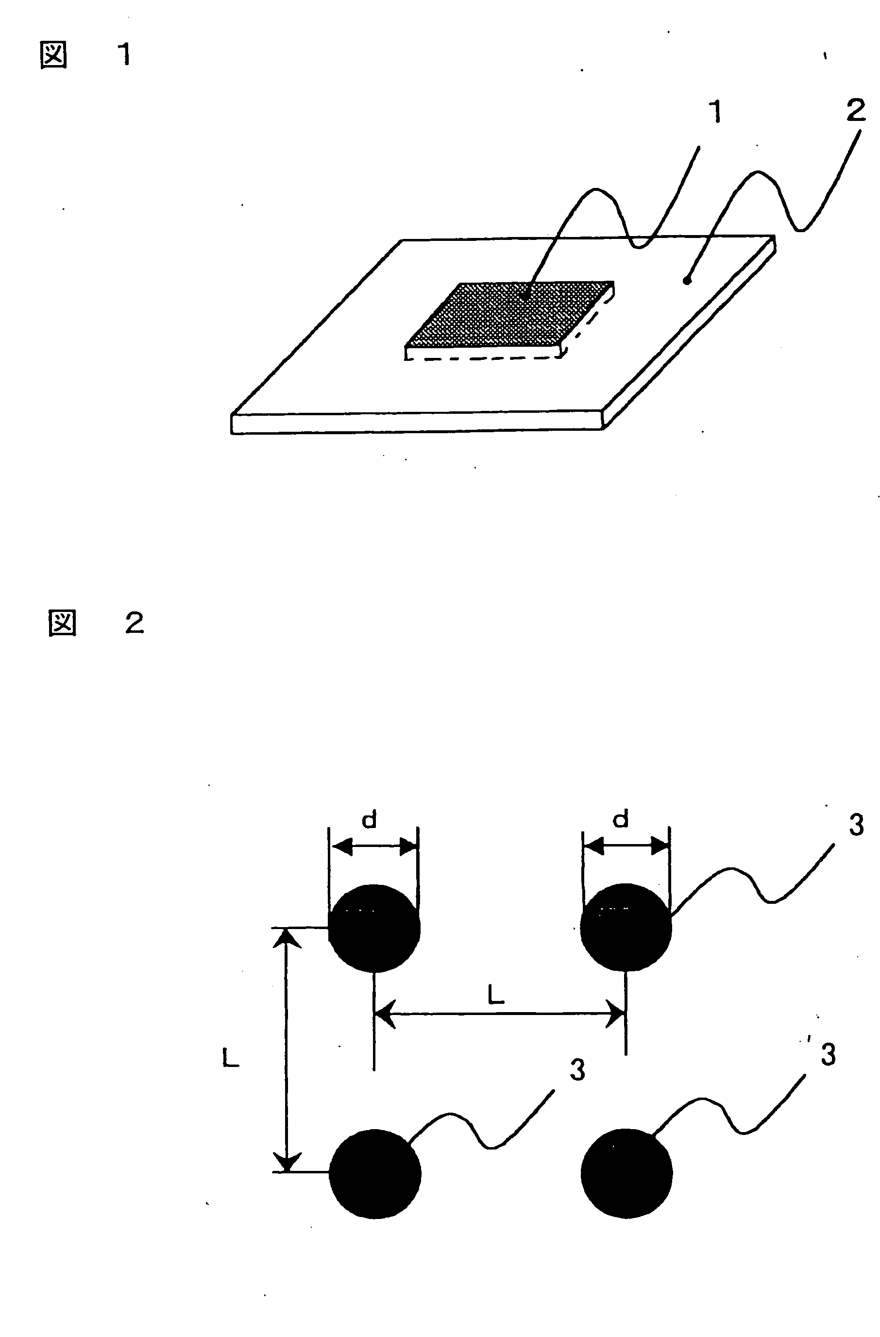
[0101] A silicon wafersilicon wafer was coated with negative-type photosensitive polyimide by spin coating and pre-baked at 110° C. The silicon wafersilicon wafer was radiated through a photo mask, developed, washed and then full-baked at 350° C. The above was submerged into hydrofuluoric acid solution, and the porous polyimide film was obtained by exfoliation from the silicon wafersilicon wafer. The obtained film is as shown in FIG. 1, wherein the porous polyimide film was a square shape with the external size of 8 cm×8 cm and the thickness of 10 μm; the porous area (1) in the center was a square with the external size of 2.2 cm×2.2 cm and the porous area (1) was surrounded by non-porous area (2). The porous area (1) was bored with collimated pores (3) whose diameter d was about 12 μm, wherein the center distance of the collimated pores L was about 33 μm, the porosity about 11% and the number of the collimated pores about 442,000. The relati...

example 2

[0108] (1) Preparation of Multipore Film

[0109] A silicon wafersilicon wafer was coated with negative-type photosensitive polyimide by spin coating and pre-baked at 110° C. The silicon wafersilicon wafer was radiated through a photo mask with the pore disposition represented in FIG. 7, developed, washed and then full-baked at 350° C. The above was submerged into hydrofuluoric acid solution, and the porous polyimide film was obtained by exfoliation from the silicon wafersilicon wafer. The obtained film is as shown in FIG. 1, wherein the porous polyimide film was a square with the external size of 8 cm×8 cm and the thickness of 10 μm; the porous area (1) in the center was a square had external size of 2.2 cm×2.2 cm and the porous area (1) was surrounded by non-porous area (2). The porous area (1) was bored with the collimated pore (3) whose diameter d was 12 μm, wherein the porosity and the number of the collimated pores were about 11% and about 440,000, respectively. The relative sta...

example 3

[0120] (1) Preparation of Multipore Film

[0121] The porous polyimide film was prepared pursuant to processing (1) of Example 1. The porous area (1) of the obtained film was bored with collimated pores (3) whose diameter d was 20 μm, wherein L, the center distance of the collimated pores, the porosity and the number of the collimated pores were about 32 μm, about 30% and about 480,000, respectively. The pore disposition was the same as that of Example 1. The relative standard deviation (LVar / LAve) was 0.16 with calculations of LAve, the average of L the center distances between adjacent collimated pores and its standard deviation, LVar.

[0122] (2) Preparation of PEM

[0123] PEM was prepared using the porous polyimide film that was processed by charging the multipore film of the above processing (1) with the proton conductor Nafion polymer as in Example 1. The membrane thickness was about 35 μm.

[0124] (3) Preparation and Evaluation of PEFC

[0125] MEA was prepared by sandwiching PEM of...


PUM

PropertyMeasurementUnit
Pore sizeaaaaaaaaaa
Porosityaaaaaaaaaa
Molar densityaaaaaaaaaa

Abstract

The polymer electrolyte membrane (PEM) of the present invention charged with a proton conductor in the collimated pores of a polymer film that is equipped with a plurality of such collimated pores in the direction of the film thickness is characterized with a relative standard deviation (LVar/LAve) equal to or below 0.3 wherein LAve and LVar represent an average value of L, distances between centers of the adjacent collimated pores and the standard deviation thereof, respectively. In addition, the PEM of the present invention can be prepared by installing a plurality of pores in the polymer film in the direction of the film thickness using photolithography and, subsequently, charging the above collimated pores with a proton conductor. Such constitution of the present invention can provide PEM with a small size, and improved performance and productivity; and also improvement of cell performance by inhibiting methanol permeation of DMFC that uses methanol as its fuel.

Description

FIELD OF THE INVENTION [0001] The present invention relates to a polymer electrolyte membrane (PEM), a method of production thereof and a polymer electrolyte type fuel cell (PEFC) using the same. [0002] A fuel cell is an electric power-generating device that is relatively environment friendly due to its low waste-production and high energy-efficiency. Therefore, fuel cells have been receiving wide attention as interest in global environment protection has been recently growing. The fuel cell, when compared with conventional large-scale electric power-generating equipment, is a promising electric power-generating device for relatively small-size distribution electric power-generating equipment and for vehicles such as automobiles and vessels. It is also getting attention for its use as an electric power source for small vehicles and portable units, and expected installation in mobile phones or personal computers as replacement of secondary cells such as Ni—H 2 or lithium ion batterie...

Claims


Application Information

Patent Timeline
CPCH01M8/0291H01M8/1009H01M8/1023H01M8/1039Y02E60/523H01M8/1062H01M8/1067H01M8/1079H01M8/106H01M8/0289Y02E60/50Y02P70/50H01M8/10
Inventor KIDAI, MASAYUKIKONO, SHUNJIYOKURA, MIYOSHIUETER, TAKAO
Owner TORAY IND INC
Why Eureka
Try Eureka