Joint mechanism

a joint mechanism and bendable technology, applied in the field of bendable joint mechanisms, can solve the problems of incongruity between the motion of the human joint and the motion of the joint the cost of the joint mechanism, and the discomfort or awkwardness of the wearer

Active Publication Date: 2015-07-02
HONDA MOTOR CO LTD
View PDF10 Cites 32 Cited by
  • Summary
  • Abstract
  • Description
  • Claims
  • Application Information

AI Technical Summary

Benefits of technology

[0099]Hence, the magnitude of the tension applied to the flexible lengthy member can be changed also according to the twenty-ninth aspect of the invention or the thirtieth aspect of the invention. Further, in the twenty-ninth aspect of the invention or the thirtieth aspect of the invention, the locking mechanism may adopt a configuration in which the flexible lengthy member is mechanically locked by recession and projection fitting or the like, thus permitting a smaller design that does not require a large driving force.

Problems solved by technology

Accordingly, an attempt to generate power for assisting the bending and stretching at such a joint by a joint mechanism having a fixed single joint tends to cause a situation in which the motion of a human joint and the motion of the joint of the joint mechanism do not fully match.
This frequently causes a person wearing the joint mechanism to feel uncomfortable or awkward mainly due to a force acting to interfere with a desired motion of the joint.
However, if a dedicated joint mechanism were prepared for each individual, then the joint mechanism would be costly.
Further, if the structure of a joint mechanism were designed to be adjustable for each individual, then the structure of the joint mechanism would tend to be complicated or become larger.
In addition, there would be some cases where the joint mechanism could not be satisfactorily suited to each individual, depending on his or her body shape or the like.

Method used


Image

  • Joint mechanism
  • Joint mechanism
  • Joint mechanism

Examples


first embodiment

[0111]A first embodiment of the joint mechanism in accordance with the present invention will be described below with reference to FIG. 1 to FIG. 7.

[0112]The joint mechanism of the present embodiment is a joint mechanism used for a walking assist device for assisting a person with his or her walking motion and the like.

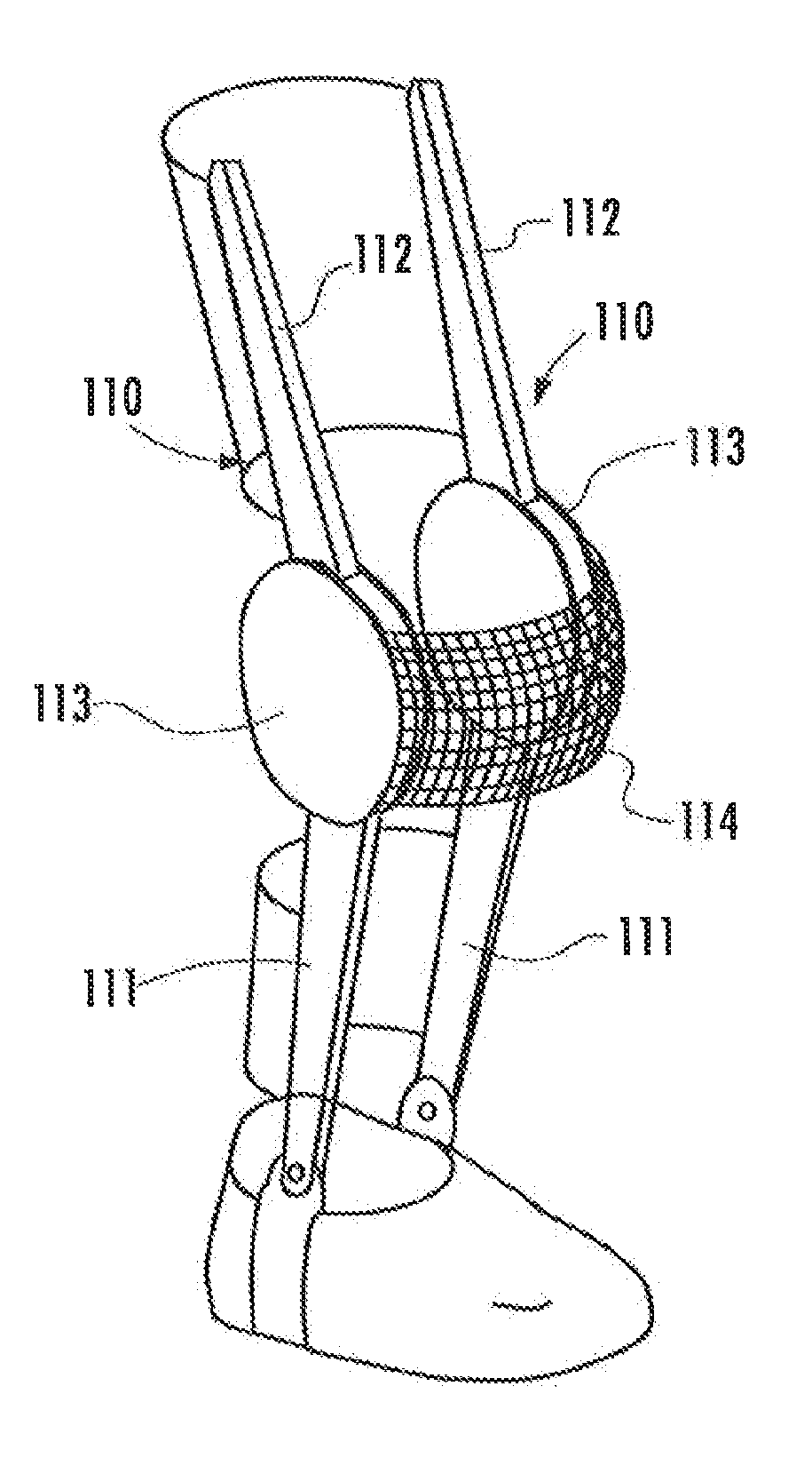
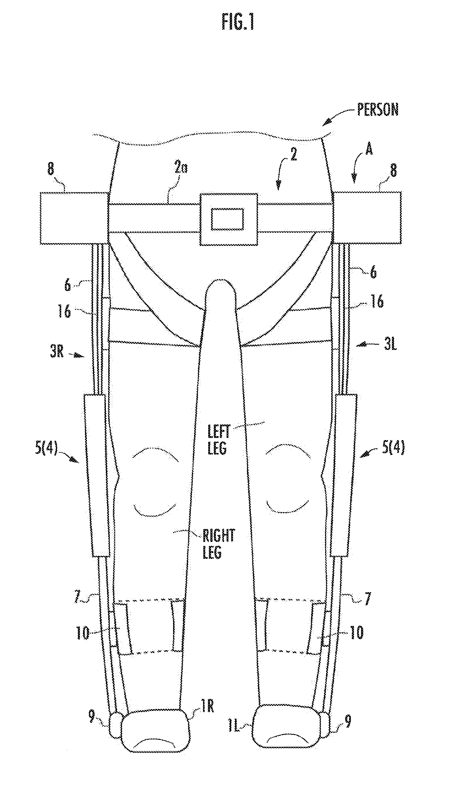
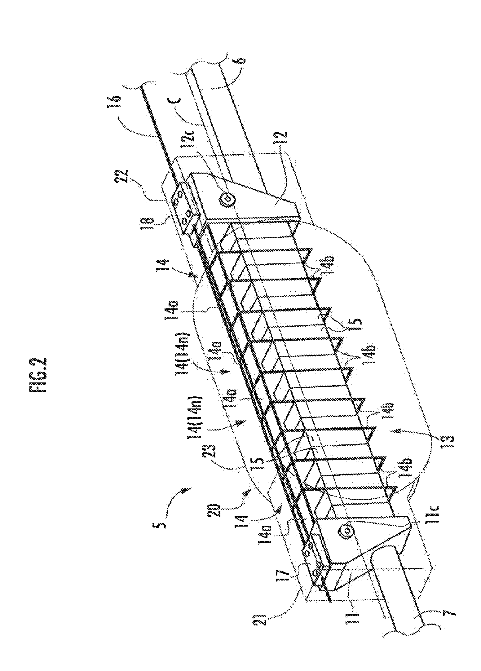
[0113]FIG. 1 illustrates a schematic configuration of the walking assist device. As illustrated, a walking assist device A has foot-worn portions 1L, 1R attached to left and right feet, respectively, of a person, a waist-worn portion 2 attached to the waist of the person and the neighborhood thereof, and legs 3L, 3R disposed to extend along and on the outer sides of the left and right legs of the person. Each of the legs 3L, 3R incorporates a main body 5 of a joint mechanism 4 (hereinafter referred to as “the joint mechanism main body 5”).

[0114]The suffixes L and R as in the foot-worn portions 1L, 1R are used as the reference characters denoting members on the left si...

second embodiment

[0233]Referring now to FIG. 8A, FIG. 8B and FIG. 8C, a second embodiment of the present invention will be described. The joint mechanism of the present embodiment differs from the foregoing embodiment only in the configuration of a joint mechanism main body. For this reason, the description of the present embodiment will be focused on the aspects that are different from the first embodiment, and the description of the same aspects as those of the first embodiment will be omitted.

[0234]As illustrated in FIG. 8A, FIG. 8B and FIG. 8C, a joint mechanism main body 65 of the present embodiment includes a first member 66 having the lower frame 7 extended therefrom, a second member 67 having the upper frame 6 extended therefrom, and a zigzag structure 68 that extends in a zigzag pattern from the first member 66 toward the second member 67 and which connects the first member 66 and the second member 67 in a relatively displaceable manner.

[0235]The first member 66 and the second member 67 are...


PUM


Abstract

A joint mechanism 4 has a zigzag structure 13 extending in a zigzag pattern between a first member 11 and a second member 12. A flexible lengthy member 16 fixed to the first member 11 extends from the first member 11 toward the second member 12 and is travelable with respect to the second member 12. A tension application unit 30 that applies a tension to the flexible lengthy member 16 is configured to be capable of changing a tension to apply.

Description

BACKGROUND OF THE INVENTION[0001]1. Field of the Invention[0002]The present invention relates to a bendable joint mechanism.[0003]2. Description of the Related Art[0004]Hitherto, as a bendable joint mechanism, there has generally been known one that has a single rotating shaft (joint shaft), i.e. a one-degree-of-freedom rotary type joint mechanism. In this type of joint mechanism, two members are connected so as to be relatively rotatable about a single rotating shaft.[0005]For example, Japanese Patent Application Laid-Open No. 2012-90849 describes a knee joint of a walking assist mechanism that uses the one-degree-of-freedom rotary type joint mechanism described above.[0006]Meanwhile, a joint, such as a human knee joint, does not have a fixed single joint axis, and the position of an instantaneous rotational center changes to accomplish bending at the joint.[0007]Accordingly, an attempt to generate power for assisting the bending and stretching at such a joint by a joint mechanism ...

Claims


Application Information

Patent Timeline
Patent Type & Authority Applications(United States)
IPC IPC(8): A61F5/01
CPCA61F2250/0012A61F5/0123A61F2005/0141A61F2005/0148
Inventor TAKENAKA, TORUGOMI, HIROSHIUEBAYASHI, YUICHIIKEDO, YOSUKEKATAGIRI, KENICHI
Owner HONDA MOTOR CO LTD
Why Eureka
Try Eureka