[0012]This makes it possible to design the induction module according to the invention to be extremely small, resulting in corresponding cost advantages. The invention therefore combines the advantages relating to good response during operation with low procurement and installation costs. A further
advantage of the invention is that it makes use of the inductance, which exists in any case, in the
transmission line, for
voltage reduction. It can therefore be implemented efficiently and at low cost.
[0013]In one preferred embodiment of the invention, the induction module is in the form of a
transformer, to be more precise an induction
transformer, which is distinguished in that the
stray inductance of the
transformer is based substantially on magnetic stray fields in the air. These are not subject to saturation. A transformer such as this is therefore particularly suitable for short-circuit operation, since the
magnetic circuit does not need to be designed on a more stringent basis, as in the case of inductors based on magnetic cores. This makes it possible to thermally and magnetically overload such transformers to a very major extent, at least for short-term operations. Small, low-cost transformers can therefore be provided for the overvoltage protective device according to the invention. This results in a further
advantage of the arrangement according to the invention, specifically that the arrangement in the spur line makes it possible to ignore any no-load losses which may occur, for magnetic design purposes, since no current flows through the transformer during normal operation, because of the spur line.
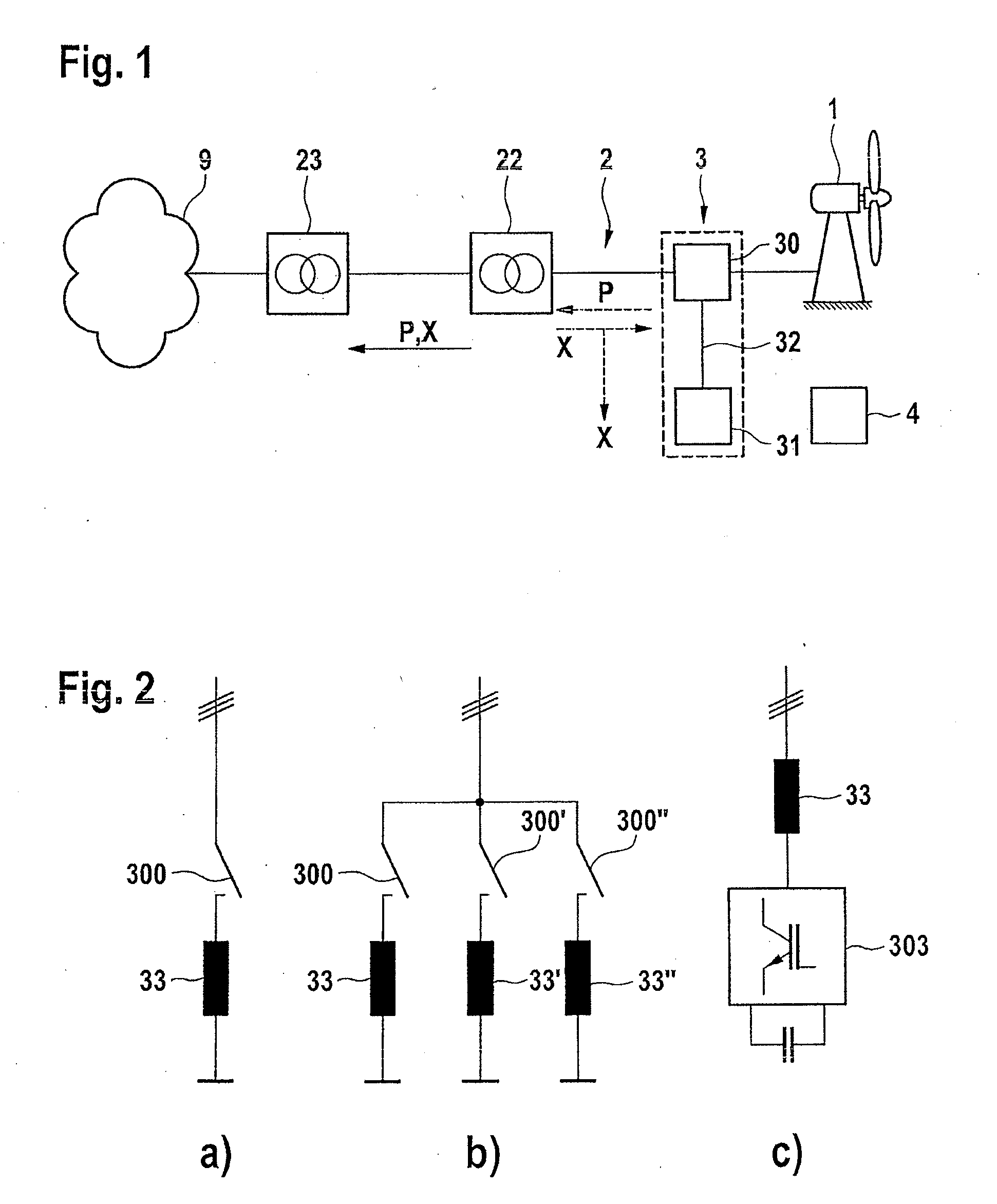
[0014]The switch is preferably in the form of a quick-acting switch. In this case, this means that it switches on within a few milliseconds, that is to say within a maximum of 10 milliseconds. In this case, the switch may be in the form of an intermediate switch. This means that it is arranged between the induction module and the connecting point of the power tapping module to the
transmission line. Normally, this arrangement is designed in this way. However, this is not essential, and instead it is also possible to provide, depending on the version of the induction module, for the switch to be in the form of a short-circuiting switch on the module.
[0015]The switch is preferably in the form of a
thyristor switch, which offers the
advantage of a very
fast switching speed, which may be 1 ms or less. Bearing in mind the grid
system frequency, this means that the
thyristor switch switches on with virtually no detectable
delay. The
thyristor switch is expediently combined with a parallel
contactor. This is designed to accept the current from the thyristor switch during longer-lasting operation. In this case, longer-lasting means operation for at least 100 ms. The parallel
contactor can also be designed using
semiconductor technology, for example with an IGBT, or else to be self-controlling, with a
varistor or a
Zener diode.
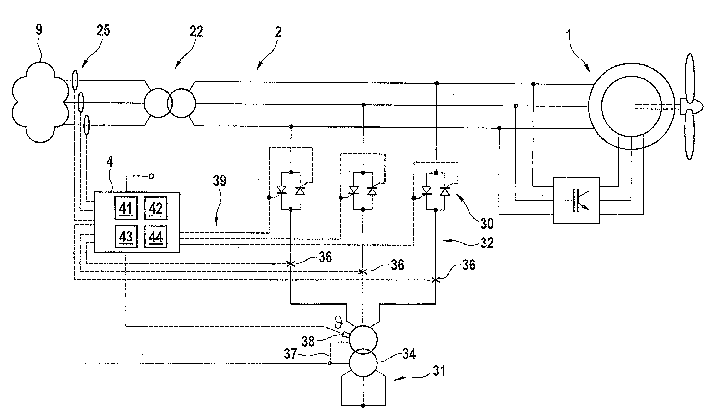
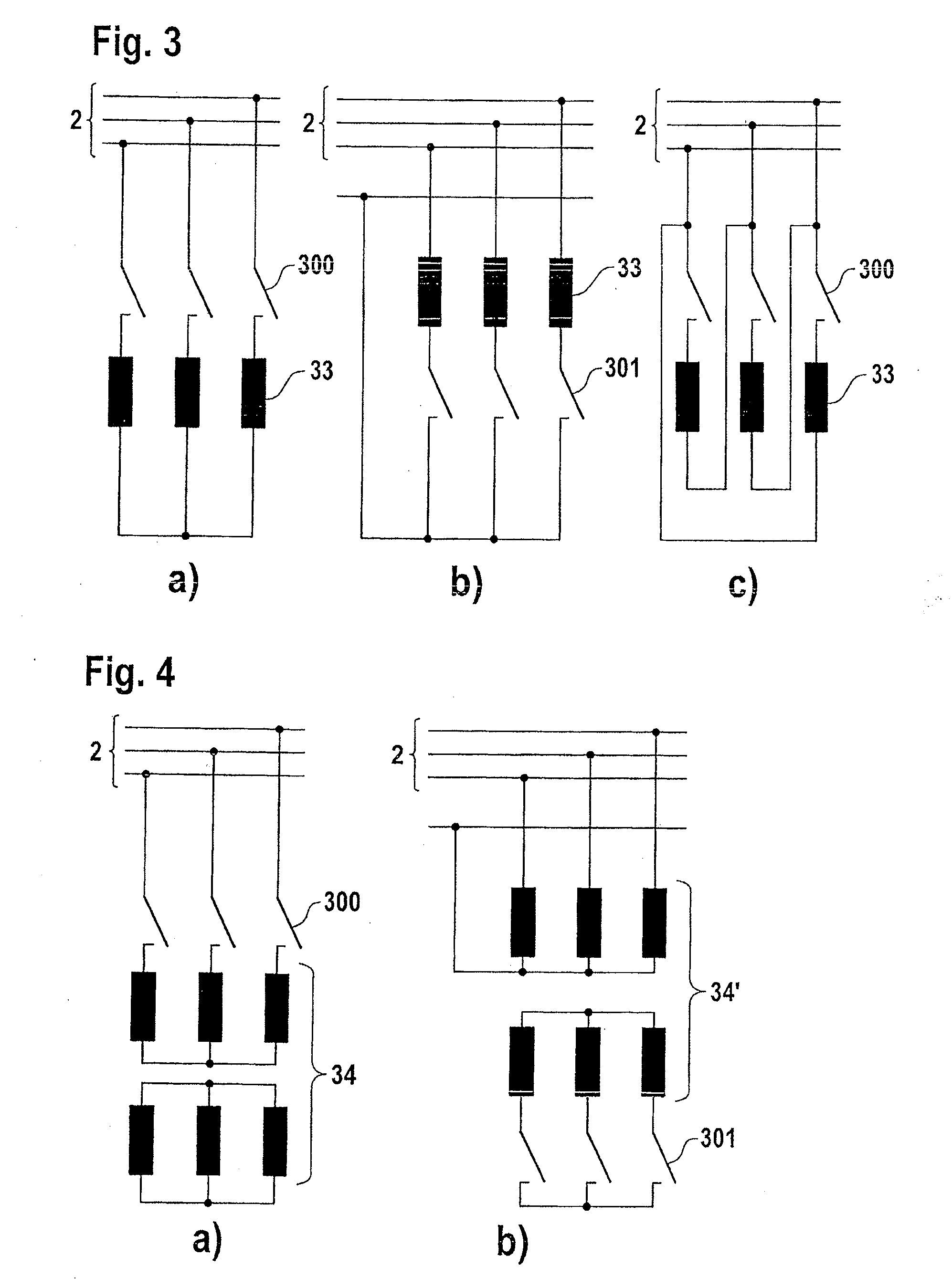
[0016]In many cases two thyristors which are provided, arranged back-to-back in parallel, for each phase. It is expedient to arrange switches which are connected back-to-back in parallel in what is referred to here as an economy circuit. This means that the switches are provided in only two of three phases of a three-phase system. The current flow in all three phases can therefore be switched using a smaller number of switches. According to one refined embodiment, switches are arranged in what is referred to here as a super economy circuit. This means that two switches, which are connected back-to-back in parallel, are not interconnected, but that the individual phases are connected to one another by thyristor switches on only one side. This minimizes the number of switches required, while nevertheless safely disconnecting the current.
[0017]A further embodiment option for the switches, in particular a configuration as short-circuiting switches, comprises them as a
bridge circuit. Six switches can therefore be arranged as a fully controlled bridge, by way of example six thyristor switches as a fully controlled thyristor bridge for short-term operation. A half-controlled bridge can also be provided, for simplicity, in which three switches, instead of six, and three diodes, in addition, are used for a passive
rectifier.

