Fuel injection device for internal combustion engines

a fuel injection device and internal combustion engine technology, applied in the direction of fuel injection pumps, machines/engines, electric control, etc., can solve the problems of limited control effectiveness of valves and difficult to achieve high switching speed, and achieve the effect of increasing switching speed and widening the cross-section of through flow

Inactive Publication Date: 2000-05-30
ROBERT BOSCH GMBH
View PDF5 Cites 56 Cited by
  • Summary
  • Abstract
  • Description
  • Claims
  • Application Information

AI Technical Summary

Benefits of technology

It is a principal object of fuel injection device according to the invention that with the aid of the control valve, a greater through flow cross section can be produced, which permits a rapid opening and closing of the injection valve member, and a small electrically controlled pre-control valve is used to switch the control valve that makes the large through flow cross sections available. Since a piezoelectric drive mechanism is additionally used to actuate the valve member of the pre-control valve, an increased switching speed can be achieved.

Problems solved by technology

Since the 3 / 2-way control valve in the known fuel injection device is actuated directly by the actuator of an electromagnet, the known fuel injection device has the disadvantage that the stroke of the valve member of the 3 / 2-way control valve and therefore the control effectiveness of the valve is limited.
With the known fuel injection device, due to the use of an electromagnet, it is particularly difficult to achieve a high switching speed, especially if the intent is to use this device for the injection of a small pre-injection quantity and then a large main injection quantity via the fuel injection valve, therefore the control valve must consequently be opened and closed twice for this procedure.

Method used


Image

  • Fuel injection device for internal combustion engines
  • Fuel injection device for internal combustion engines

Examples


Embodiment Construction

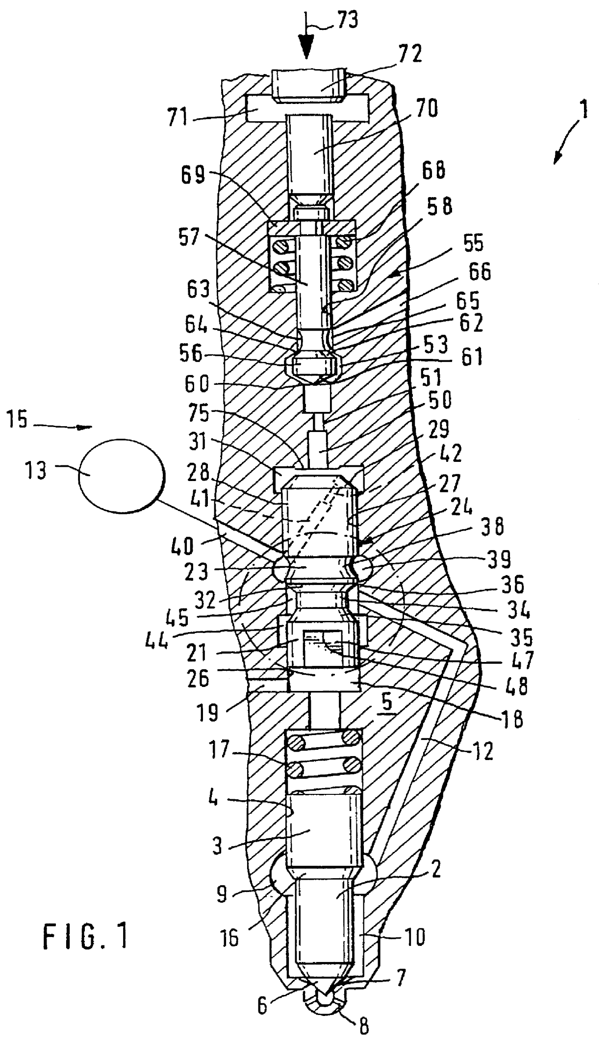
The fuel injection valve 1 depicted in FIG. 1 has a fuel injection valve member 2, which is guided with a guide part 3 in a bore 4 of a fuel injection valve housing 5. At one end of the fuel injection valve member, it has a sealing face 6, which can be brought into contact with a valve seat 7 on the housing and thereby separates fuel injection openings 8 from a pressure chamber 9, which extends to the valve seat 7 in the form of an annular chamber 10 around the end of the fuel injection valve member 2. The pressure chamber 9 can be connected to a high-pressure fuel source 13 via a pressure conduit 12 and a control valve 15. Fuel that has been brought to injection pressure is always available in the high-pressure fuel source.

In the region of the pressure chamber 9, the injection valve member has a pressure shoulder 16 by means of which it can be opened away from the valve seat 7 for the purpose of injection with the pressurization of the pressure chamber 9, counter to a closing sprin...


PUM


Abstract

PCT No. PCT/DE98/00945 Sec. 371 Date Jun. 30, 1999 Sec. 102(e) Date Jun. 30, 1999 PCT Filed Apr. 3, 1998 PCT Pub. No. WO99/15783 PCT Pub. Date Apr. 1, 1999A fuel injection device for internal combustion engines is proposed in which a fuel injection valve is controlled by the pressure in a pressure chamber, which acts on a pressure shoulder in its opening and closing direction. The pressure supply to the a pressure chamber is controlled by a control valve member which in turn is moved by a pressure in a working chamber. The pressure in the working chamber is controlled by a pre-control valve which has a closing body which, through the influence of the piezoelectric drive mechanism, is moved from a second valve seat to a first valve seat and thereby momentarily opens a relief line of the working chamber. This movement results in an opening of the control valve member and a supplying of high fuel pressure to the pressure chamber for purposes of injection. Thus a very small pre-injection quantity is produced. In order to produce a main injection quantity, the closing body is positioned in an intermediate position between the valve seats and a longer connection of the high-pressure fuel supply to the pressure chamber is consequently produced.

Description

The invention is directed to improvements on a fuel injection device for internal combustion. In a fuel injection device of this kind, which is known from EP 0 657 642, the high-pressure fuel source is comprised of a high-pressure fuel pump, which delivers fuel from a low-pressure chamber into a high-pressure accumulation chamber, which is connected by way of pressure lines to individual injection valves that protrude into the combustion chamber of the engine to be supplied, wherein the common pressure storage system (common rail) is kept at a particular pressure level by means of a pressure control device. In order to control injection times and injection quantities, an electrically controlled control valve is provided to each of the injection valves and controls the high-pressure fuel injection with its opening and closing. The control valve in the known fuel injection device is embodied as a 3 / 2-way valve that connects a pressure conduit, which feeds at the injection opening of t...

Claims


Application Information

Patent Timeline
Patent Type & Authority Patents(United States)
IPC IPC(8): F02M59/00F02M63/00F02M59/46F02M45/04F02M45/00F02D41/20F02M51/00F02M45/08F02M61/16
CPCF02M45/04F02M63/0007F02M63/0029F02M63/0005F02D41/2096F02M2200/703F02M63/00
Inventor BOECKING, FRIEDRICH
Owner ROBERT BOSCH GMBH
Why Eureka
Try Eureka